1
\$\begingroup\$

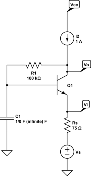
How can I solve this circuit?

schematic

simulate this circuit – Schematic created using CircuitLab

This capacitor confuses me when I tried to do DC biasing.

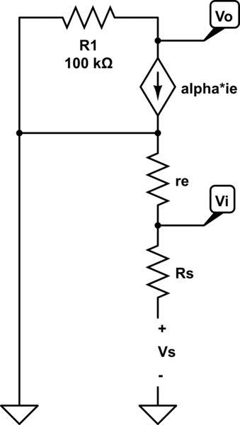
Also when I draw small signal equivalent circuit( T model ) to find the equation for Rin (=re) and Rout(=R1) but not Av ( voltage gain ) and Ai (current gain ). here is my small signal equivalent circuit:

schematic

simulate this circuit

\$\endgroup\$
7
  • \$\begingroup\$ I'm unsure what you are trying to solve - you have a constant current generator in the collector and the collector itself will act as a high compliance current source and this means the normal assumptions about simple transistor models tend to rely on knowing the current gain of the transistor (which is unknown in your circuit) \$\endgroup\$
    – Andy aka
    Commented Apr 28, 2014 at 18:14
  • \$\begingroup\$ No more information is provided in the question. But we can assume beta=100. \$\endgroup\$
    – Anklon
    Commented Apr 28, 2014 at 18:21
  • \$\begingroup\$ Your circuit makes no sense. With infinite capacitance on the base, the base voltage will forever stay at whatever the initial conditions are, which you haven't stated. Of course infinite capacitance is urealistic anyway, so it's hard to say what the point is. \$\endgroup\$ Commented Apr 28, 2014 at 18:52
  • 1
    \$\begingroup\$ I think infinite capacity here is to be interpreted as an open for DC bias calculations and a short for small signal calculations. \$\endgroup\$
    – jippie
    Commented Apr 28, 2014 at 19:05
  • 1
    \$\begingroup\$ @AlfredCentauri ; Vs is the AC small signal source. \$\endgroup\$
    – Anklon
    Commented Apr 29, 2014 at 2:32

2 Answers 2

1
\$\begingroup\$

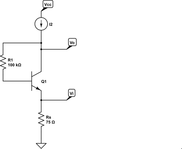
As always, it's helpful to first draw the DC and AC circuits.

DC circuit:
schematic

simulate this circuit – Schematic created using CircuitLab

The operating point is evident by inspection:

$$I_C = \frac{\beta}{1 + \beta}I_2 = \alpha I_2 $$

$$V_C = I_C(\frac{75\Omega}{\alpha} + \frac{100k\Omega}{\beta}) + V_{BE} $$


Update to address comment:

I can't perfectly grasp your equation for Vcc.I think understand you divide resistance with beta and alpha to make them equivalent resistance looking through C.

Assuming you meant \$V_C\$ rather than \$V_{CC}\$, by KVL we have

$$V_C = V_E + V_{BE} + V_{R1}$$

We have

$$V_E = I_E R_S = \frac{I_C}{\alpha}R_S $$

and

$$V_{R1} = I_B R_1 = \frac{I_C}{\beta}R_1$$

Thus

$$V_C = I_C(\frac{R_S}{\alpha} + \frac{R_1}{\beta}) + V_{BE} $$


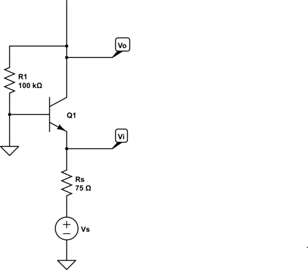
AC circuit:
schematic

simulate this circuit

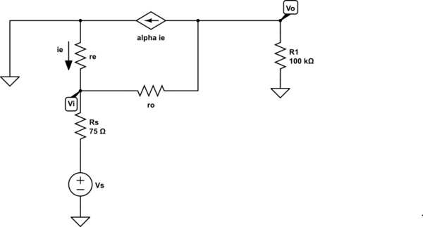
The small-signal circuit is thus
schematic

simulate this circuit

This is a straightforward circuit to solve. What have you tried so far?
\$\endgroup\$
8
  • \$\begingroup\$ Why would you leave Vs in small-signal? Voltage sources become shorts in AC small-signal analysis. \$\endgroup\$
    – horta
    Commented Apr 28, 2014 at 20:53
  • 1
    \$\begingroup\$ @horta, it seems reasonable to me that the OP intends \$V_S\$ to be the signal voltage source which does not become an AC short in small-signal analysis. Otherwise the circuit has no small-signal source and the small-signal solution is the trivial one. \$\endgroup\$ Commented Apr 28, 2014 at 20:59
  • \$\begingroup\$ Vs is obviously different than Vi because there's a node Vi for the input voltage. In small-signal analysis, you use test voltages and/or test currents to determine the characteristics of the circuit (Av,Ai,Rin, and Rout). All current sources become opens and all voltage sources become shorts in SS analysis. \$\endgroup\$
    – horta
    Commented Apr 28, 2014 at 21:08
  • \$\begingroup\$ @horta, I'm quite well aware of how to do small-signal analysis and I disagree with your interpretation of the schematic. For me, it's obvious that \$R_S\$ is the source resistance and thus, the small signal input voltage is, as typically understood, \$v_i = v_s \frac{r_{in}}{R_S + r_{in}}\$. Look at any voltage amplifier model and you typically see that the input voltage is not the source voltage but is the source voltage reduced by the voltage divider formed by the source resistance and the input resistance. For example: i.sstatic.net/vvjgi.png \$\endgroup\$ Commented Apr 28, 2014 at 21:17
  • 1
    \$\begingroup\$ @Anklon, the equation is for the collector voltage \$V_C\$, not \$V_{CC}\$. For this circuit, the only equation we have for \$V_{CE}\$ is \$V_{CE} = V_C - V_E\$ and finding these two voltage is trivial. Ordinarily, there is a resistor between the collector and \$V_{CC}\$ and we can easily find \$V_C = V_{CC} - I_CR_C\$. In this case, I simply found \$V_E = I_E R_E = \frac{I_C}{\alpha}R_E\$, added \$V_{BE}\$ and the voltage across \$R_1\$. It is customary to guess a \$V_{BE}\$ between 0.65V and 0.75V for BJT DC analysis. The guess can be refined if necessary but typically it isn't. \$\endgroup\$ Commented Apr 29, 2014 at 11:19
-1
\$\begingroup\$

In small signal, your Vs becomes a short.

Make sure you're not confusing the T and pi models. Here's a good reference: http://www.ittc.ku.edu/~jstiles/412/handouts/5.6%20Small%20Signal%20Operation%20and%20Models/The%20Hybrid%20Pi%20and%20T%20Models%20lecture.pdf

Lastly, determine what Vout/Vin is (Av) and Iout/Iin (Ai).

Also, I doubt your Rin and Rout are so simple. To obtain those, you'll need to apply a test voltage or test current to the input and solve for the other one. Then you'll have Vin/Iin = Rin and Vout/Iout = Rout. When dealing with voltage dependent current sources like you have, you almost always need to factor that into the problem which is why you need to solve using test voltages/currents.

\$\endgroup\$

Your Answer

By clicking “Post Your Answer”, you agree to our terms of service and acknowledge you have read our privacy policy.

Not the answer you're looking for? Browse other questions tagged or ask your own question.