1
\$\begingroup\$

This is related to an earlier question of mine, but I have a different follow-up question that I wanted to make a new post for.

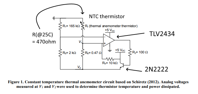
I'm trying to understand more about how the below circuit works, specifically the amplifier:

enter image description here

Taken from here with some extra details added. EDIT: Was able to find the source document here, in case that's useful to anybody.

I've tried implementing something similar with an instrumentation amp, but was told that an opamp would be a much better choice. However, I'm not totally clear about how the opamp is functioning in this context. This doesn't appear to be set up like a difference amplifier with gain-limiting feedback resistors, and it was suggested that large gain is actually beneficial here. So here's what I don't understand:

  • Is this opamp configured to act as a comparator here? I.e., is the amplifier output primarily going to be saturated near 5V or ground most of the time, and avoid intermediate output voltages?

  • If it's acting as a comparator, what happens when the bridge is balanced? The thermistor should be held at an elevated temp when this happens, so would we essentially see a square wave at the opamp output?

  • If this isn't acting as a comparator, how is the gain being set?

Sorry for what might be a simple misunderstanding - I'm just having a hard time wrapping my head around the intended operation as I'm used to simpler opamp circuits.

TLV2434 data sheet

2N2222 data sheet of sorts.

\$\endgroup\$
5
  • 1
    \$\begingroup\$ What are you trying to achieve wit this circuit? Your comments about thermistor heating capacity suggest use as a heater rather than it's original purpose as an air speed detector. Telling us what your application and real problem is would help heaps. | Why do you care how much heat is added to the thermistor - saturation should be addressed by applying less power - IF you are using it an intended. || Q1 the 2N2222 is simply a current amplifier for the opamp to give it enough power to drive the NTC. \$\endgroup\$
    – Russell McMahon
    Commented May 7, 2020 at 0:00
  • \$\begingroup\$ That's correct - I'm just looking to measure airspeed. My understanding is that a higher working temperature allows for faster response to transient changes in velocity since it's less dependent on the thermal time constant of the thermistor itself (I may be mistaken, and I'm definitely not explaining that well in any event). In the example I've linked above, they're heating it to about 75 deg C, which is set through the resistor ratio in the non-thermistor leg of the bridge (it heats until they match, if possible). If you have any thoughts on that issue I'd definitely appreciate it. \$\endgroup\$
    – Silver
    Commented May 7, 2020 at 0:18
  • 1
    \$\begingroup\$ With 5V operation the max a thermistor at 40 Ohms can dissipate is V^2/R ~= 600 mW. Selecting an thermistor that matches your requirement at say 100-200 mW should be "easy enough". Have you got a thermistor part number / link? || 2N2222 is rated at 500 mA. What are you actually using? Link? The circuit should be easy enough to make operate. (Should be). Note that inputs to opamp need to be <= 4.5V. common mode range. \$\endgroup\$
    – Russell McMahon
    Commented May 7, 2020 at 0:28
  • \$\begingroup\$ Agreed, I definitely need to change the resistor values - I'm still piecing together how to best optimize the ratio. I'm using a TIP31G (3A continuous) - I noticed that as well and was worried about the current limit so I switched it. I picked up a thermistor kit since I wasn't sure which values would be most appropriate - I have all of the ones listed here and I've been trying to use the 40, 100, and 1k ohm ones so far, since most of the examples I've seen have been on the lower end, I thought to facilitate heating \$\endgroup\$
    – Silver
    Commented May 7, 2020 at 0:39
  • \$\begingroup\$ The design is "somewhat strange" \$\endgroup\$
    – Russell McMahon
    Commented May 7, 2020 at 3:10

3 Answers 3

2
\$\begingroup\$

Ignoring R4 for the moment, its effect is negligible, I don't understand what its purpose is. Edit: Necessary to boot the circuit (thanks Transistor).

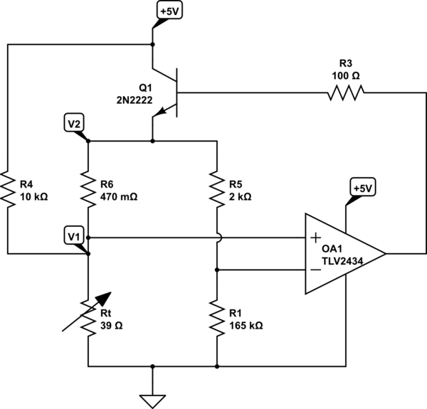
The circuit is not functioning as a comparator. The closed loop circuit will attempt to balance the inputs of the opamp. It will adjust the voltage at V2 until the self-heating of the thermistor causes the thermistor resistance to be about 39 ohms.

Redrawing the circuit makes it easier to understand.

schematic

simulate this circuit – Schematic created using CircuitLab

Edit: This circuit may work in a laboratory environment, but I question its usefulness in the real world. On a cold day, I doubt that you can ever get enough power into the thermistor to warm it up. The thermistor's resistance on a cold day might be 1k. 5V^2/1k is only 25 mW.

\$\endgroup\$
5
  • 1
    \$\begingroup\$ R4 boots the circuit up. If, on power-up, Q1 is off there is no voltage or very little then Vin- > Vin+ and the circuit won't start. R4 biases the circuit so that Vin+ > Vin-, the op-amp output switches high and the rest is as you have written. Interestingly I had also corrected the schematic with positive supply on top very similar to yours. \$\endgroup\$
    – Transistor
    Commented May 6, 2020 at 21:14
  • \$\begingroup\$ Thanks both of you for the detailed information - that helps a lot (I upvoted but apparently I'm short on rep to have it show up yet). I suppose trying to look at it in terms of gain the way you'd look at an opamp with feedback resistors would be misleading in this case. So the voltage measured at the output (and the bridge "top" voltage) will both rise until either equilibrium is reached or the maximum possible emitter current is flowing. I just recreated this with a slightly different thermistor and bridge ratio, and I appear to already be saturating before hitting the target temp. \$\endgroup\$
    – Silver
    Commented May 6, 2020 at 21:57
  • \$\begingroup\$ Regarding both my saturation issue and real-world usefulness, what would you recommend to improve heating capability? Increasing the excitation voltage, or possibly use of a smaller R25 thermistor? Or perhaps use of a Darlington pair instead of a single NPN transistor? \$\endgroup\$
    – Silver
    Commented May 6, 2020 at 21:59
  • 1
    \$\begingroup\$ To get more heating capability, use a higher Vcc, maybe 15V. You will need to use a different opamp with a higher Vcc capability. It needs to be a rail-to-rail opamp. A darlington won't help. \$\endgroup\$
    – Mattman944
    Commented May 6, 2020 at 22:37
  • \$\begingroup\$ That makes sense - thanks for the explanation! \$\endgroup\$
    – Silver
    Commented May 7, 2020 at 0:19
1
\$\begingroup\$

Following up on Mattman944, the transistor is needed to provide the high current needed to heat the sensor/thermistor.

\$\endgroup\$
1
  • \$\begingroup\$ Thanks for the clarification. It looks like the transistor is going to be the main limiting factor in terms of usefulness, as mentioned above. I need look into ways of increasing current delivery, because the transistor I used to replicate this (2N3904) isn't quite cutting it. \$\endgroup\$
    – Silver
    Commented May 6, 2020 at 22:04
1
\$\begingroup\$

The design is "somewhat strange" and seems to suffer from over-cleverness. An attempt has been made to drive a bridge with a self regulating supply but the result depends on components used and is hard to design, whereas a simplification may make it easier to design. See below.

The operating point is not well defined as V2 can assume a range of values with the bridge in balance. It IS a comparator circuit but the gain is set by the ratio of the transistor driven network to R4 which is hard to analyse simply.

Using lower thermistor resistances changes the DC operating point. Lowering R4 to keep it in the same in the same ratio to the thermistor "may help". Lowering the thermistor value only risks driving the inverting input out of Vcm range.
I suggest that making the ratio of R1:R5 NO GREATER than about 8:1 looks wise. That means that the inverting input can never be driven above (5-0.6) x R5/(R1+R5) ~= 4V which is well within the opamps common mode range.

If the 5V is stable then connecting R5 to +5V rather than to V2 will probably operate correctly without any "magic" as at present. The thermistor current and operating point can then be designed with confidence.
If the 5V supply is too variable do as above but clamp inverting input with a zener or reference source. (A TL431 0.5% part gives good stability at minor cost).
In both cases R4 is no longer needed.

The document that you refer to mentions a "constant voltage thermistor circuit". Adding the divider or reference as above makes it so. The originally cited source was absent when I looked for it. It would be interesting to see if somebody can find a copy.

\$\endgroup\$

Your Answer

By clicking “Post Your Answer”, you agree to our terms of service and acknowledge you have read our privacy policy.

Not the answer you're looking for? Browse other questions tagged or ask your own question.