After a few tutorials, I'm writing my first VHDL entity of my own.
Given an input signal and a 50MHz clock, it's supposed to emit a 6-clock-pulse strobe (120μs) when the time between two transitions in the input signal is longer than 21 clock pulses (420μs), and emit nothing if the transitions are shorter.
It revolves around a 5-bit binary counter. At each clock pulse it samples the input signal and compares it with the previous sample to see if a transition has occurred. If no change, keep counting; otherwise, set the strobe high if the counter reached 21, and reset it in any case. Also reset the strobe at the sixth clock pulse after the last transition.
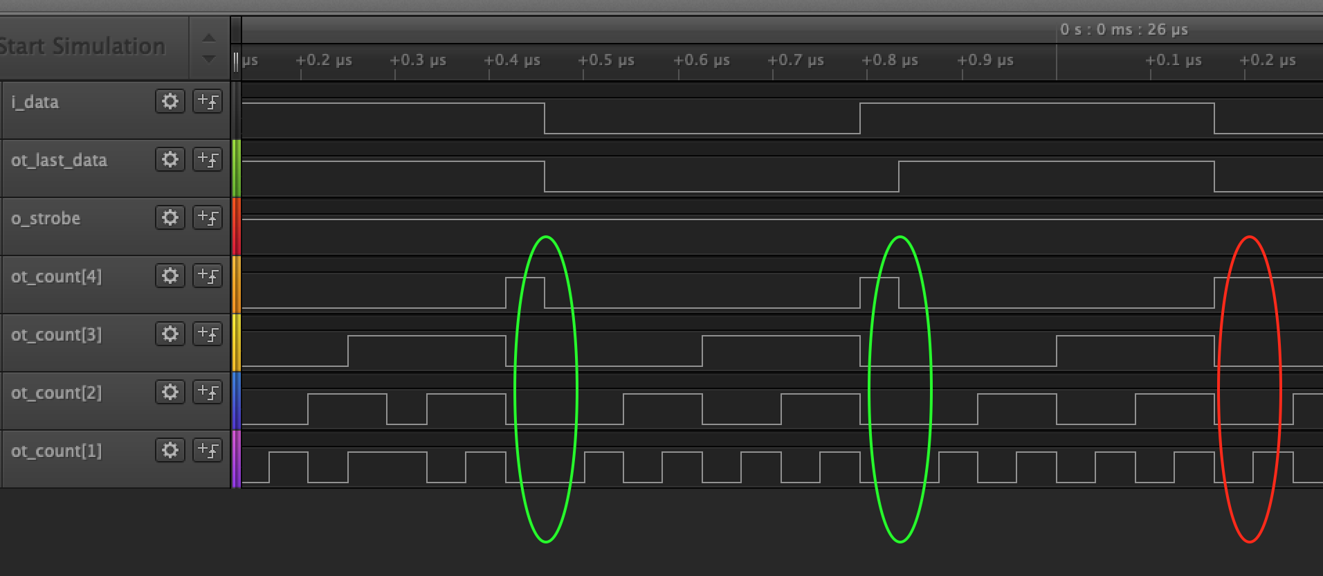
While it works fine in ModelSim (using a stimulus taken from a real-world signal), IRL it often fails to recognize a transition, causing problems downstream. Here's a screenshot from the logic analyzer:
Here the pulses are shorter, and the counter is supposed to reset at 16-17 (note the bit 0 isn't shown, it switches too quickly for my 24Msps logic analyzer). I'd expect the counter ot_count to reset at every transition of i_data/ot_last_data, but sometimes it keeps counting.
Here's the code:
library ieee;
use ieee.std_logic_1164.all;
use ieee.std_logic_unsigned.all;
use ieee.numeric_std.all;

entity SpdifAmp is
    port(
        i_clock: in std_logic;
        i_data: in std_logic;
        o_strobe: out std_logic;
        ot_last_data: out std_logic;
        ot_count: out std_logic_vector (4 downto 0)
    );
end SpdifAmp;

architecture rtl of SpdifAmp is
    signal r_last_data : std_logic := '0';
    signal r_count : std_logic_vector (4 downto 0);
    signal r_strobe : std_logic := '0';
    constant c_zeros : std_logic_vector(r_count'range) := (others => '0');

begin
    SyncFinder : process(i_clock, i_data, r_strobe, r_count, r_last_data)
    begin
        if rising_edge(i_clock) then
            if i_data = r_last_data then
                r_count <= r_count + 1;
                if r_count = 6 then
                    r_strobe <= '0';
                end if;
            else
                if r_count > 21 then
                    r_strobe <= '1';
                end if;

                r_count <= c_zeros;
                r_last_data <= i_data;
            end if;
        end if;
        o_strobe <= not r_strobe;
        ot_last_data <= r_last_data;
        ot_count <= r_count;
    end process SyncFinder;
end rtl;
Seems like the if i_data = r_last_data then is under some race condition; being new to VHDL I don't understand what's wrong and how to fix this.

