Sup, guys. I'm in the violent war with PIC MCUs and they're clearly winning, so I'm asking once again for your intellectual support.
I have PIC16F877A on a breadboard, external 8Mhz+2x20pf, bypassed, Vpp pulled up with 47k. Windows 10, MPLAB X 5.40, XC8 2.20.
I finally got the stuff running, turned out I had breadboard side issues all the time and not lack of IQ, my code was actually correct all the time (which I realized with half of my hair already pulled out). Now I blink like a boss, so I decided to connect to common 0.96 inch OLED (I have ssd1306 datasheet). The OLED is connected appropriately, powered etc. I2C has 10k pullups that worked like a charm for me in other non-PIC projects with the very same OLED.
I feel comfortable around datasheets and registers.
So I found a nice vid and followed it with MCU's datasheet open on the 2nd monitor to make sure I understand what I'm doing. Good news: I understand what I'm doing. Bad news: it doesn't work.
This is the vid: PIC I2C
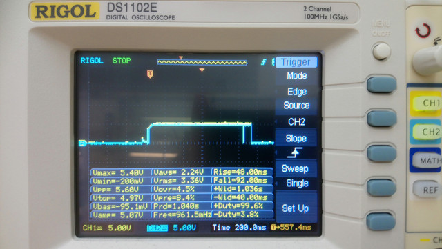
I have an oscilloscope, so I hooked up to SCL and SDA, set up a trigger and saw this wonderful thing:
Considering it's already second PIC MCU where I can't get I2C running (the other one is PIC16F18326). For starters, I just want to see some communication and not a flatline. I use LED at RC6 pin for debugging to make sure the code reaches certain part and doesn't lock somewhere up and loop forever. So far, the LED always goes off:
You'll probably want to see my code, there you go:
// PIC16F877A Configuration Bit Settings

// 'C' source line config statements

// CONFIG
#pragma config FOSC = HS        // Oscillator Selection bits (XT oscillator)
#pragma config WDTE = OFF       // Watchdog Timer Enable bit (WDT disabled)
#pragma config PWRTE = OFF      // Power-up Timer Enable bit (PWRT disabled)
#pragma config BOREN = OFF      // Brown-out Reset Enable bit (BOR disabled)
#pragma config LVP = ON         // Low-Voltage (Single-Supply) In-Circuit Serial Programming Enable bit (RB3/PGM pin has PGM function; low-voltage programming enabled)
#pragma config CPD = OFF        // Data EEPROM Memory Code Protection bit (Data EEPROM code protection off)
#pragma config WRT = OFF        // Flash Program Memory Write Enable bits (Write protection off; all program memory may be written to by EECON control)
#pragma config CP = OFF         // Flash Program Memory Code Protection bit (Code protection off)

#include <xc.h>
#include <htc.h>
#include <stdio.h>
#include <stdint.h>

#define _XTAL_FREQ 8000000


void i2c_is_idle(void){
    PORTCbits.RC6=1; //RC6 LED ON
    while(SSPCON2bits.SEN==1 || SSPCON2bits.RSEN==1 || SSPCON2bits.PEN==1 || SSPCON2bits.RCEN==1 || SSPCON2bits.ACKEN==1 || SSPSTATbits.R_nW==1){};
    PORTCbits.RC6=0; //RC6 LED OFF
}

void i2c_start(void){
    i2c_is_idle();
    SSPCON2bits.SEN = 1;
}

void i2c_rep_start(void){
    i2c_is_idle();
    SSPCON2bits.RSEN = 1;
}

void i2c_stop(void){
    i2c_is_idle();
    SSPCON2bits.PEN = 1;
}

void i2c_write(uint8_t i2c_data){
    i2c_is_idle();
    SSPBUF = i2c_data;
    while(SSPSTATbits.BF != 0);
    while(SSPCON2bits.ACKSTAT != 0);
}

uint8_t i2c_read(uint8_t ack){
    uint8_t recieve =0;
    i2c_is_idle();
    SSPCON2bits.RCEN = 1;
    while(SSPSTATbits.BF != 1);
    recieve = SSPBUF;
    SSPCON2bits.ACKEN = ack;
    return recieve;
}

void i2c_init(void){
    TRISCbits.TRISC3 = 1;
    TRISCbits.TRISC4 = 1;

    SSPSTATbits.SMP = 1;
    SSPSTATbits.CKE = 0;
    SSPCONbits.SSPM = 0x08;
    SSPADD = 19;
    SSPCONbits.SSPEN = 1;

}

void main(void) {
    TRISC = 0x00;
    ADCON0 &=0b11111110;
    i2c_init();

    //__delay_ms(1);
    while(1){
    __delay_ms(20);
    PORTCbits.RC6=1; //RC6 LED ON
    __delay_ms(10);
    i2c_start();
    i2c_write(0x3C);
    i2c_stop();
    }
    return;
}
So yeah, the LED goes off. The funny thing is that while my I2C is in a forever while loop, SCL and SDA go up to 5V, sit there for a few hundred ms and then sit firmly at 0V.
Tbh, I'm totally lost and I have no idea what I'm doing wrong. Any help would be appreciated. Help me save the rest of my hair please :D


while(!PIR1bits.SSPIF);, which seems to indicate all the relevant events, for now at least. You'll need to clear it everytime afterwards of course. Even if there's no slave present, you should still see some activity on those lines. You should also connect your LED up to the scope to be sure it toggles continuously. \$\endgroup\$