0
\$\begingroup\$

I found the following data slicer circuit:
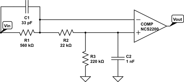
schematic

simulate this circuit – Schematic created using CircuitLab

The input is a simple NRZ (PAM-2) signal between "Vhigh" and "Vlow" (=around 0V) where each bit has a length "Tbit". Due to bandwidth limitation, the input is also not a perfect square pulse but can be modeled as being filtered with a simple first-order lowpass with cutoff "fc".

I can't wrap my head around why exactly the author or this circuit came up with the idea of adding R1+C1 (and R3). I cannot find a single where adding R1+C1 would not make things worse (after all, it's a highpass/differentiator). Similarly, I neigher see the purpose for R3, nore can I find a case where it would be helpful.

In LTspice, the circuit works best if I kick out R1,C1 and R3 and make R2*C3 = 5/Tbit (as suggested in https://www.maximintegrated.com/en/design/technical-documents/app-notes/3/3671.html).

But I don't want to remove just just because I don't understand it...

EDIT: Maybe this was a "hard" question so I changed it to merely understand what this thing is doing...

\$\endgroup\$
4
  • \$\begingroup\$ It all depends on how much you want to 'slice'. You'd need to know how you want to change the waveform and generate requirements for that. In short, you need to know Vin and Vout then you can define the transfer function of the opamp. \$\endgroup\$
    – Voltage Spike
    Commented Jul 15, 2020 at 20:19
  • \$\begingroup\$ I am sorry if the question was not quite clear but this is exactly my question: If I give you Vhigh and Vlow (and Tbit and fc and possibly the bit pattern) HOW do I set R1,C1,R2,C2,R3 and possibly the hysteresis of the comparator? (EDIT: I can add a picture of a sample signal) \$\endgroup\$
    – divB
    Commented Jul 15, 2020 at 20:28
  • \$\begingroup\$ Note that the NCS2200 is a low voltage comparator with a 1 uS response time, but with proper RC values it should be able to handle high baud rates under 115 Kbaud. It is specific to being a ultra-low power comparator for battery devices. \$\endgroup\$
    – user105652
    Commented Jul 15, 2020 at 21:12
  • \$\begingroup\$ Any idea what the differentiator (R1+C1) could be good for? Why do we need R3? All slicers I find are much more simple and would only consist of R2 and C2... \$\endgroup\$
    – divB
    Commented Jul 16, 2020 at 5:40

2 Answers 2

1
\$\begingroup\$

R1 and C1 increase the slew rate of the signal being seen by the comparator, to make for cleaner transitions between states.

R2 and C2 establish the reference voltage used for comparisons based on the long-term DC value of the input waveform. It also prevents the reference voltage from drifting "off center" during asymmetrical input data patterns.

R3 establishes the DC operating point for the output.

\$\endgroup\$
1
\$\begingroup\$

The usefulness of a highpass or differentiator depends on your signal.

In a noisy environment a differentiator would rather harm.

But if your signal comes in too much low-pass filtered a differentiator can help to restore the edges. Basically you then place the positive edge at the onset of a positive move and vice versa.

\$\endgroup\$

Your Answer

By clicking “Post Your Answer”, you agree to our terms of service and acknowledge you have read our privacy policy.

Not the answer you're looking for? Browse other questions tagged or ask your own question.