0
\$\begingroup\$

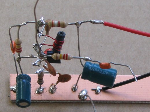
schematic bird nest

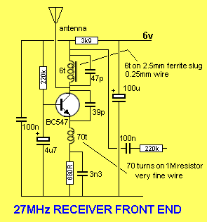
I know this circuit is an oscillator circuit and it senses another signal of same frequency, but I don't understand

  • the calculation behind it, and
  • the reason for emitter inductor,
  • 3.9k collector resistor and
  • others.

Can someone please show me the calculations for this circuit?

I made one myself but I am tired of tuning it. It only receives signal within few centimeters. It receives not only my 27 MHz toy car remote signal but any kind of signal, e.g: walkie talkie signal.

here is the link for that circuit: http://www.talkingelectronics.com/projects/27MHz%20Transmitters/27MHzLinks-1.html

They explained the circuit but didn't show the calculation, and they also didn't mention the inductor value.

#

So many ANSWERS in so little TIME. This is my first post on this site, and all of you made me feel warm, i am really honored. Thank you so much guys, and please forgive me if i said anything that hurts you. Even if i haven't found any suitable answer but i really found something that is more importent than the answer, you all waste your time for me, that's all i really needed, THANK YOU, THANK YOU AGAIN. If you know any place where i can start learning RF all over again, then feel free to mention it.

\$\endgroup\$
15
  • \$\begingroup\$ hey, welcome. We'll not explain a complex circuit that you just found anywhere and then answer another three general questions in one answer; that's just too much to ask. While certainly entertaining, your wiring is a mess and signal being picked up if the transmitter is within centimeters of this circuit has nothing to do with this circuit working as a receiver, but with the circuit being subject to interference. Start with something simpler. Also, 27 MHz antennas are relatively large or built resonantly, I see neither in your photo. \$\endgroup\$ Commented Dec 17, 2018 at 17:27
  • 3
    \$\begingroup\$ oh wait! You interpreted the schematic as wiring diagram? That is impressive, yet incorrect. The schematic is meant to show you what is connected to what, not how things are geometrically arranged. The way you've built this actually pretty much maximizes all chances for operation to go wrong. Also, how do you know your toy car remote isn't being picked up? \$\endgroup\$ Commented Dec 17, 2018 at 17:30
  • 1
    \$\begingroup\$ @MarcusMüller We owe the OP an apology. That photo is from the same website that post the schematic. That 'mess' is not the OP's creation. \$\endgroup\$
    – user105652
    Commented Dec 17, 2018 at 17:38
  • 1
    \$\begingroup\$ The emitter inductor is an RFC choke. It just blocks any RF from being shorted to ground. No value is given as it could vary by 10% with no change. You are picking up many local signals at the same time because this circuit is too simple to separate adjacent channels. \$\endgroup\$
    – user105652
    Commented Dec 17, 2018 at 17:51
  • 1
    \$\begingroup\$ @raddevus It's soldered to a strip of un-etched PCB. That's actually not a bad way to prototype analog circuits up to around 50MHz if you know what you're doing, although the usual way to do it is to have the circuit no more than one layer above the board. Google "dead bug construction" for how-to's (and probably better examples than this one). \$\endgroup\$
    – TimWescott
    Commented Dec 17, 2018 at 20:39

2 Answers 2

2
\$\begingroup\$

That's a super-regenerative receiver, very commonly used in toy car receivers.
That construction technique may look messy, but it is OK for 27 MHz frequency. The major difficulty is ensuring:

  • the 6 turn coil on the ferrite slug resonates (with 47pf + a bit more) @ 27 MHz.

  • the whole thing oscillates at a frequency usually in the 20kHz - 50 kHz ballpark.

That 70-turn coil attached to the emitter is involved with the 50 kHz oscillation. Its value might be in the 3uH to 5 uH ballpark. You can use a molded fixed inductor here.
The 47 pf, 39pf, plus antenna length affect the 27 MHz. resonant frequency. Most often, the collector coil has an adjustable slug to set this frequency very close to 27 MHz. These receivers use a short antenna that appears as a capacitive reactance - its length affects 27 MHz frequency. Your receiver is likely insensitive, because this frequency is somewhere else.
An oscilloscope is very useful to ensure that this oscillator is oscillating at both high frequency (27MHz) and low frequency (50 kHz) at the same time.
You should notice that the 50 kHz frequency becomes higher when a 27 MHz signal from a transmitter is present. Look at the transistor emitter to see this.

\$\endgroup\$
3
  • \$\begingroup\$ This was a crude way of doing things for a few decades. Today, it's arguably cheaper (and a lot easier) to pair nRF24L01+ clone modules with small MCUs and make the equivalent of what used to be a several hundred dollar digital PCM R/C aircraft control. Even $12 toys work this way now - more reliable, interference almost entirely hidden, shorter antennas, no frequency coordination issues and a near arbitrary number of high resolution high speed channels effectively for free. Wheras the pictured circuit would still need encoder and decoder for each individual control function. \$\endgroup\$ Commented Dec 17, 2018 at 18:14
  • \$\begingroup\$ @ChrisStratton Crude? OK that's true (this receiver radiates an interfering signal at 27 MHz) - but for its part-count it can be quite sensitive. Your "module" idea has validity and more versatility - if you're a programmer too. \$\endgroup\$
    – glen_geek
    Commented Dec 17, 2018 at 18:27
  • \$\begingroup\$ These systems can work but what is pictured is only about 1/4 over the overall problem, and as the asker is finding out, very touchy to implement. What's nice about the 2.4 GHz digital chips and software is that they're fairly easy to replicate and don't require any tuning or adjustment. There have been some horribly bad projects using them published of course, but if one finds a good tutorial or example and replicates it, it just works, and is easily customized. It's also pretty easy to switch example project allegiance just by changing software and maybe moving the SPI pins connections. \$\endgroup\$ Commented Dec 17, 2018 at 18:38
0
\$\begingroup\$

If you really want to understand how super regenerative circuits work I suggest you do a web search on "super regenerative receiver theory of operation", then read the articles that you find most accessible. The best treatments may well be the ones that are reprints of articles from the 1920's or 1930's featuring vacuum tubes -- the superregen is old technology, and was, for a time high technology. However, by the time transistors came along is was usually the domain of cheap radios, made by incurious people who just wanted to make a buck.

Don't be surprised to see superregen designs with two oscillators -- it's actually easier to understand a circuit that has a separate quench and receiver oscillator (and it usually makes a better receiver). Most modern superregens are made to be minimal-cost, so they'll just have one amplifying element.

Two characteristics of superregens is that when tuned correctly they're almost supernaturally sensitive, and unless you take superhuman measures (like RF filters way bigger than today's digital receivers) they are, by today's measures, insanely broad in their response. The former quality is good, and back in the day when the bands were uncrowded made the rest worthwhile. The latter quality is bad, and can't be overlooked today, unless you live in the middle of nowhere.

\$\endgroup\$
6
  • \$\begingroup\$ The asker should think about if they want to understand this particular circuit, or build a circuit to accomplish remotely operating something - as today those two goals point in extremely different directions of effort. \$\endgroup\$ Commented Dec 17, 2018 at 19:53
  • \$\begingroup\$ ok I understand, thank you. if this design is too old, then i am leaving it. If you know any modern scematics of tx rx then please give me that link, maybe this could solve my problem. I know about colpitts oscillator, i think i can build transmitter using it, but what about receiver? \$\endgroup\$
    – Curious
    Commented Dec 17, 2018 at 20:22
  • \$\begingroup\$ If you want to learn and design receivers, then an ARRL handbook and Experimental Methods in RF Design, and accept that you'll spend a lot of time to build something much bigger, more expensive, and simpler than what you can just buy. If you want RF blocks to solve problems, then buy pre-made RF modules that let you stick data in and get data out. \$\endgroup\$
    – TimWescott
    Commented Dec 17, 2018 at 20:43
  • \$\begingroup\$ @Curious - the board design shown in the nRF24L01+ data sheet is commonly available as an assembled module (with an alternate chip) for $1-2/ea. It can be used as any of transmitter, receiver, or both. Use that on each end with 3v3 Arduino Nano or a bare $1 MCU of your choice to do the signal encoding/decoding. Building a comparably capable radio at any frequency from building-block parts would be far more complicated and costly. \$\endgroup\$ Commented Dec 17, 2018 at 21:42
  • \$\begingroup\$ @Chris Stratton, nRF24L01 cos $12 in our country, but thank you for recommended this to me. I think building is most effective way of learning than buying, so i made a choice 1 year ago that i will build a pair of tx rx by myself. Thanks to both of you. \$\endgroup\$
    – Curious
    Commented Dec 18, 2018 at 4:27

Your Answer

By clicking “Post Your Answer”, you agree to our terms of service and acknowledge you have read our privacy policy.

Not the answer you're looking for? Browse other questions tagged or ask your own question.