2
\$\begingroup\$

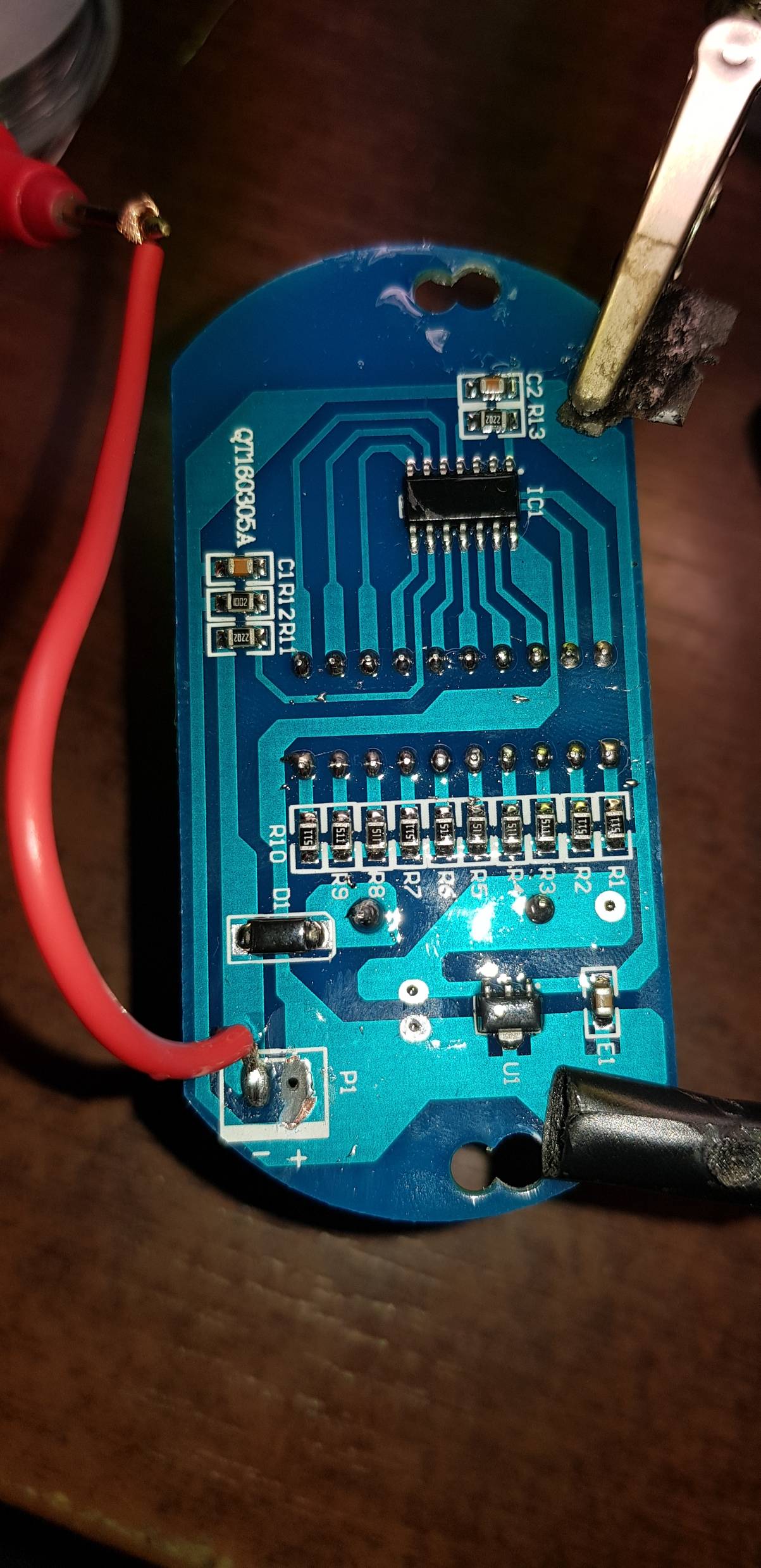
I've been asked to reattach the positive cable that got ripped with the pad from a board given that I own a soldering iron. It seems simple enough to just jump it from a trace.

Scraped a bit of the mask off from the pad space at P1, yet I don't get anything at all while measuring for continuity from the negative cable to the exposed trace.

The whole board is covered in some resin if that helps.

As I see it the big traces starting in P1 are clearly separated so those should be the negative and positive sides so the magic pixies should go from one side to the other, but they seem real lazy.

What am I not understanding?

enter image description here

Edit: this board is for showing battery level on some boat, theres a counter soldered on the other side

\$\endgroup\$
4
  • 3
    \$\begingroup\$ You should not get continuity between the + and - traces, that would be a short-circuit. Your meter should read some resistance value... \$\endgroup\$
    – Ron Beyer
    Commented Aug 18, 2020 at 13:55
  • \$\begingroup\$ You shouldn't be measuring for continuity to the red wire, it might not have a low resistance path. Measure for continuity between the exposed copper on the + pad and the large pin on U1. \$\endgroup\$
    – Justin
    Commented Aug 18, 2020 at 13:55
  • 1
    \$\begingroup\$ The "resin" covering the board is an epoxy, it's called "solder mask". It helps to keep errant solder from flowing where you don't want it. It's easy to remove. Get a (sharp new) xacto knife, and DRAG it across the area you want to remove... Not cutting, dragging. The solder mask will shatter when you do it right, and you won't be damaging the copper underneath. You have a huge area there to practice on! Good luck \$\endgroup\$
    – Kyle B
    Commented Aug 18, 2020 at 14:13
  • \$\begingroup\$ Kyle B -huh, i always though the solder mask was the green/blue colored one that covers the traces. Am i correct? The resin i was talking about is another clear coat on the entire top side of the board, components included, sorry if i worded my post badly. Thanks for the comment tho! \$\endgroup\$
    – Dimon
    Commented Aug 18, 2020 at 14:31

3 Answers 3

1
\$\begingroup\$

The resin is most likely some kind of conformal coating, which shouldn't be a big deal. If you are trying to measure continuity, you can follow the + trace to other components on the board. R12, C1, and C2 all have leads that touch the + trace, so once you have re-soldered the wire (next to the "+" pad) you can check continuity between the wire and one of these components.

\$\endgroup\$
1
  • 1
    \$\begingroup\$ Yeah it probably is conformal coating, makes sense now that i know its part of a boat. Resoldered the wire, checked for continuety at C2 and it seems fine, shows 0 on one pin and 560~ on the pin closer to the C2 marking. This was very helpful, thanks! Now to get some comformal coating \$\endgroup\$
    – Dimon
    Commented Aug 18, 2020 at 15:27
1
\$\begingroup\$

Power on P1 is connected but GND is not on the other pin (black Wire?)

Ensure you have continuity using a needle elsewhere to GND and clean P1 pad with razor blade scrapes lightly.

Lightly surface coat with solder without filling hole. (Solder tin coat each before bonding preferably using the hole.)

Insert short solid wire in hole, fold and solder. Then reconnect to short solid wire with heat shrink using mechanical twist strength and minimum solder to coat surfaces.

Then for final strength add a dab of sub-floor adhesive and let that be your strain relief like plastic insulation and mechanical support with electrical insulation .

Then you can yank the wire pair as hard as would want if lightly coated from PCB P1 to a couple cm or 1” away.

They use white stuff inPSU’s for big leaded parts but it not avail in DIY shops yet subfloor adhesive Polyurethane is dirt cheap in a tube but the non-volatile stuff these days takes a day to get to -≈50% hardness exposed to air and harder after that. when tapered you have perfect strain relief. Apply like paste with a disposable tool.

\$\endgroup\$
0
\$\begingroup\$

There shouldn't be "continuity" between the two pins for P1. You'll probably be able to measure some kiloohms of resistance between the two, but that won't tell you anything useful.

P1 has two pins, marked "+" and "-". You've got the red wire attached to "-". I hope that doesn't mean you connected the positive wire of a power supply to the minus pin. If you did, then you might have killed the circuit.

The "+" wire was torn off. It was connected to the large area to the right of the torn pad. You should be able to just scrape some solder mask off of that large area and solder down the wire.

The board might be double sided, though, so you'll have to flip it over and see what's on the other side of the torn pad. If there's nothing there, good. If there's another trace leaving from the top side, though, then you'll have to add another wire from the large "+" area that goes around to the other end of the torn pad on the other side of the board.

\$\endgroup\$
3
  • \$\begingroup\$ Why shouldnt there be continuety for the two pins at P1? Or should i just get an electronics 101 book? Seems to be one sided(cant figure out how to include an image in the comment) theres only the counter and a resistor on the other side, their pins go straight through the board. Thought reattaching the wire would be good enough because see bad fix bad, id just like to know how to check if it should work before giving it away. Thanks for the comment tho, damn you guys here are quick to respond! \$\endgroup\$
    – Dimon
    Commented Aug 18, 2020 at 14:46
  • \$\begingroup\$ If there were continuity between "+" and "-" then you'd short circuit your battery (or what ever power source you use) evert time you hook it up. "Continuity" is a test for a "short circuit" and you use it to see if a wire or trace conducts electricity. \$\endgroup\$
    – JRE
    Commented Aug 18, 2020 at 14:57
  • \$\begingroup\$ That.. makes a lot of sense. Think i got a couple concepts jumbled up together, actually now i know i need to read up on some concepts, thats great help \$\endgroup\$
    – Dimon
    Commented Aug 18, 2020 at 15:53

Your Answer

By clicking “Post Your Answer”, you agree to our terms of service and acknowledge you have read our privacy policy.

Not the answer you're looking for? Browse other questions tagged or ask your own question.