2
\$\begingroup\$

enter image description here

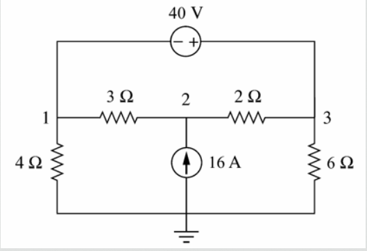
How to find the nodal voltage when there is a 40V across Node 1 & 3?

V1= 22.4 V V2= 65.6V V3= 62.4 V

My Nodal Analysis

Node 1 (SuperNode):

  • -V1/4 - V1-V2/3 + V2-V3/2 - V3/6 = 0

Node 2

  • V1-V2/3 + 16 - V2-V3/2 = 0

Constraint Equation

  • V1-V3 = 40

Any help is greatly appreciated!

\$\endgroup\$
6
  • 1
    \$\begingroup\$ Have you tried using superposition? \$\endgroup\$
    – Andy aka
    Commented Aug 30, 2020 at 8:35
  • 1
    \$\begingroup\$ This type of connection gives rise to an equation of the form \$V_3 = V_1 +40V\$. Use it along with other equations and solve as usual. \$\endgroup\$
    – AJN
    Commented Aug 30, 2020 at 8:35
  • \$\begingroup\$ @Andyaka I tried using superposition, but I didn't get the answer \$\endgroup\$
    – Dugong98
    Commented Aug 30, 2020 at 8:46
  • \$\begingroup\$ You should show what you did (put it in your question) then maybe someone can see where you went wrong. \$\endgroup\$
    – Andy aka
    Commented Aug 30, 2020 at 8:48
  • \$\begingroup\$ @Andyaka I've added my nodal analysis! Any help is greatly appreciated \$\endgroup\$
    – Dugong98
    Commented Aug 30, 2020 at 8:56

4 Answers 4

8
\$\begingroup\$

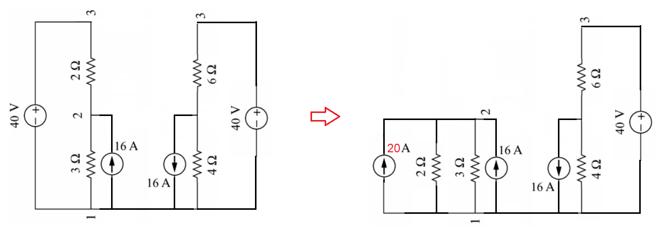
I'd just rearrange the diagram and use source-splitting techniques: -

enter image description here

From left to right, it's the same circuit but, breaking it down step by step is easier to analyse. Each step saves maths and is a pictorial record of what you did thus, making it easier to parse.

$$\boxed{\text{So, why do I prefer this method?}}$$

Well, my turn to solution is simulation (because I don't do exams any more) but, source-splitting is my 2nd choice because it's clearer at each stage and, teaches you how to properly analyse circuits using your brain. It makes you more EE savvy.

So, from the diagram on the above right, I'm going to calculate the voltage between node 1 and node 2. Note that the earth/ground point originally in the question's circuit is irrelevant here.

The 40 volt source in series with the 2 ohm resistor is equivalent to a current source of 20 amps in parallel with 2 ohms. That current source and 2 ohm resistor are now in parallel with a 3 ohm resistor and a 16 amp current source: -
enter image description here

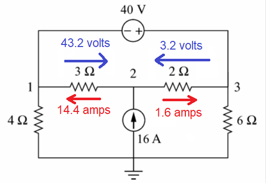
Hence, the voltage between node 1 and node 2 is

$$(20\text{ amps}+16\text{ amps})\cdot\dfrac{3\text{ ohms}\times 2\text{ ohms}}{3\text{ ohms}+2\text{ ohms}} = 43.2 \text{ volts}$$

And, if you looked at the answer given (V1= 22.4 V V2= 65.6V) that is what you see.

Then just add what you know (from one calculation) to your original circuit: -
enter image description here

And I'm going to stop here in the expectation that the OP will solve the rest.

\$\endgroup\$
3
  • \$\begingroup\$ Thanks for your very clear explanation! @Andyaka. What are the reasons why you don't use Nodal Analysis? Whenever I do nodal Analysis, I have problems finding which direction the current is flowing. whether in or out of the node? Any tips to solve such a problem? \$\endgroup\$
    – Dugong98
    Commented Aug 30, 2020 at 9:57
  • \$\begingroup\$ I don't use nodal analysis. I either solve in a simulator or use the above. \$\endgroup\$
    – Andy aka
    Commented Aug 30, 2020 at 9:58
  • 1
    \$\begingroup\$ Yep this answer is better than mine, by splitting the source he has made two Thevenin equivalents on each side , and driven each of these with 16A. Just solving massive equations all the time just makes your head ache, and you don't really understand what is happening. The general approach to all of these problems is to try and re-arrange the problem into simple solvable blocks. Save all the algebra for Laplace domain problems. \$\endgroup\$
    – BobT
    Commented Aug 30, 2020 at 10:14
3
\$\begingroup\$

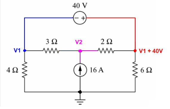
The classic book method is to use a supernode:

enter image description here

Thus we are only left with two unknowns nodal voltages \$V_1\$ and\$V_2\$

And the nodal equation for two nodes are:

\$V_1\$ Super-node, additional I assume that all current flows out from \$V_1\$ node (\$V_1\$ is the highest voltage and this is why\$V_1\$ is "always first" in the numerator).

$$\frac{V_1}{4\Omega} + \frac{V_1 - V_2}{3\Omega} + \frac{V_1+40V}{6\Omega}+ \frac{(V_1 +40V) - V_2}{2\Omega} = 0$$

And for the \$V_2\$ node, and again I assume that \$V_2\$ is the highest voltage so, all the current will flow out of the \$V_2\$ node (this is why\$V_2\$ is "always first" in the numerator).

$$\frac{V_2 - V_1}{3\Omega}+\frac{V_2 - (V_1 +40)}{2\Omega} - 16A = 0$$

So all you need to do is to solve it:

https://www.wolframalpha.com/input/?i=x1%2F4+%2B+%28x1+-+x2%29%2F3+%2B+%28x1%2B40%29%2F6+%2B+%28x1%2B40+-+x2%29%2F2%3D0%2C+%28x2+-+x1%29%2F3+%2B+%28x2+-+%28x1+%2B40%29%29%2F2+-16%3D0

And if you have time try to watch this

https://www.youtube.com/watch?v=NA_zlZTDiKU&feature=emb_logo

\$\endgroup\$
1
  • \$\begingroup\$ Thank you so much @G36 \$\endgroup\$
    – Dugong98
    Commented Aug 31, 2020 at 2:36
1
\$\begingroup\$

OK , Here is the basic method

  1. Move the ground connection to node 1 , and just call the old ground node 4
  2. Set the 40v source to zero volts, as a voltage source, it has zero ohms impedance, so this step basically shorts together nodes 1 and 3
  3. Call nodes 1+3 node 0 (i.e. ground ), you then have a current source with the positive end connected to ground via 3//2ohms and the negative end connected to ground via 4//6ohms, you can then work out currents sources contributions to each resistors voltage, write this down somewhere.
  4. Set the voltage source back to 40v , and set current source to zero , (i.e. disconnect it)
  5. Now work out the voltages across the 2 and 3 ohm resistors, should be 2/5 and 3/5 of 40v , 16v and 24v ; and the 4 and 6 ohm resistors 4/10ths and 6/10ths of 40 or 24v and 16v , write these down somewhere.
  6. Now simply add algebraically the voltages for each resistor from steps 2 and 5 , (the voltage on the 2ohm resistor will be slightly less than 16v and 3 ohm slightly more than 24v)
  7. Now subtract the voltage across the 4ohm resistor from all nodes, this will result in node 4 being at 0v , i.e. ground potential, and all the other node voltages will be the wanted voltages.

This is not the only method, but shows one way to break the problem down to manageable steps. Another approach would be to work out the thevenin equivalent of the voltage source and resistors )this will give 2 thevenin voltages and resistance, then apply the current across the thevenin equivalent and work from there. You should really try both ways. You can also convert the current source to its equivalent thevenin voltage source , then paralle both thevenin sources. You will find if you try all three methods, you will find yourself seeing the same numbers in each step. There is even a boring yet very complex way of working it out by writing equations for each resistance .

The circuit shown is actually a Wheatstone bridge, more obvious if you rotate it 90 degrees CCW.

Getting back to your working , it is common to use subscripts to denote voltages so V1 is then $V_1$ and the voltage of node 2 wrt node one is $V_1_2$

\$\endgroup\$
7
  • \$\begingroup\$ Thanks for sharing BOB, I have added my nodal analysis. But i still got the equation wrong! Care to share where i went wrong? \$\endgroup\$
    – Dugong98
    Commented Aug 30, 2020 at 8:52
  • \$\begingroup\$ Hi @Dugong98 , you wrote " V1= 22.4 V V2= 65.6V V3= 62.4 V " is this the right answer?, or your wrong answer? I'll just find a bit of paper to scribble on...... \$\endgroup\$
    – BobT
    Commented Aug 30, 2020 at 9:14
  • \$\begingroup\$ That is the right answer! Thanks a lot @BobT \$\endgroup\$
    – Dugong98
    Commented Aug 30, 2020 at 9:16
  • \$\begingroup\$ You probably have the sign wrong somewhere, that's the usual problem e.g V12 is the negative of V21. or brackets in wrong place, it would be easier to label the resistors Ra Rb Rc Rd , and the voltage across each being Va Vb Vc Vd , using the sign convention that left is negative. \$\endgroup\$
    – BobT
    Commented Aug 30, 2020 at 9:25
  • \$\begingroup\$ Ok this line is missing brackets -V1/4 - V1-V2/3 + V2-V3/2 - V3/6 = 0 , Should be -V1/4 - (V1-V2)/3 + (V2-V3)/2 - V3/6 = 0 (this is the cuurents in one side and out the other of the voltage source) \$\endgroup\$
    – BobT
    Commented Aug 30, 2020 at 9:49
1
\$\begingroup\$

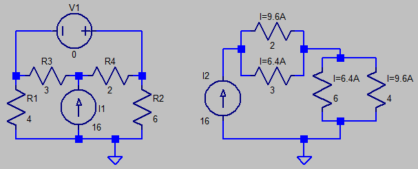
BobT's answer uses superposition. Normally, I avoid superposition because it is so very difficult to keep current directions straight, and sum them properly. It takes practice to find a way to be consistent with assigning current directions. But in this case, superposition is fairly straightforward...

First, isolate the current source by shorting the voltage source. It helps to re-draw the circuit - once you do so, solving currents becomes super-easy. 16 amps gets divided into two parts \$ \frac{2}{5}16 , \frac{3}{5}16\$:
current source acts alone
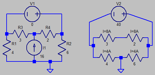
Now open up the current source, and make the voltage source active. Again redraw the circuit, which makes solving currents very straightforward. This skill of re-drawing circuits is one that needs practice. An electrical engineer is adept at re-arranging circuit components this way. Again, solving currents in the two paths is super-easy:
voltage source acting alone
Now the most difficult part is summing both together, and then assigning current direction to the final answer. Note that current directions from each source acting alone oppose each other in the 4-ohm and 2-ohm resistor. Usually, we don't write final currents as signed numbers, but translate signs to a direction - an assignment marker will appreciate this sign-assignment: it saves him/her some extra work.

\$\endgroup\$

Your Answer

By clicking “Post Your Answer”, you agree to our terms of service and acknowledge you have read our privacy policy.

Not the answer you're looking for? Browse other questions tagged or ask your own question.