0
\$\begingroup\$

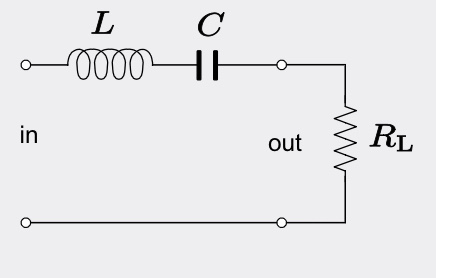
Consider the RLC band pass filter circuit:

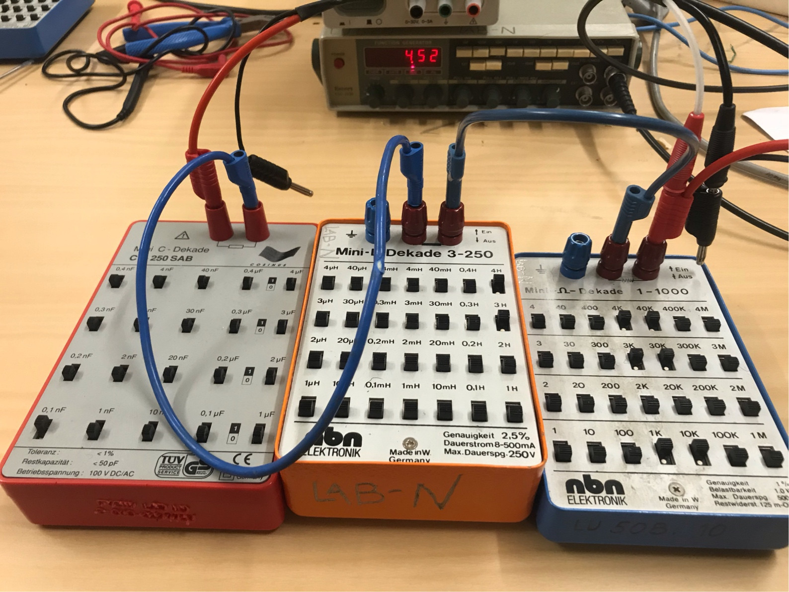
I’m trying to construct this circuit with a maximum of the transfer curve at \$f=5-6\$kHz and bandwidth \$\beta=2\pi \cdot 2\$kHz and so I have chosen a 88k\$\Omega\$ resistor, 7H inductor and 0.1nF capacitor, according to the formulas $$f=1/(2\pi \sqrt{LC})$$ and $$\beta=R/L \ .$$

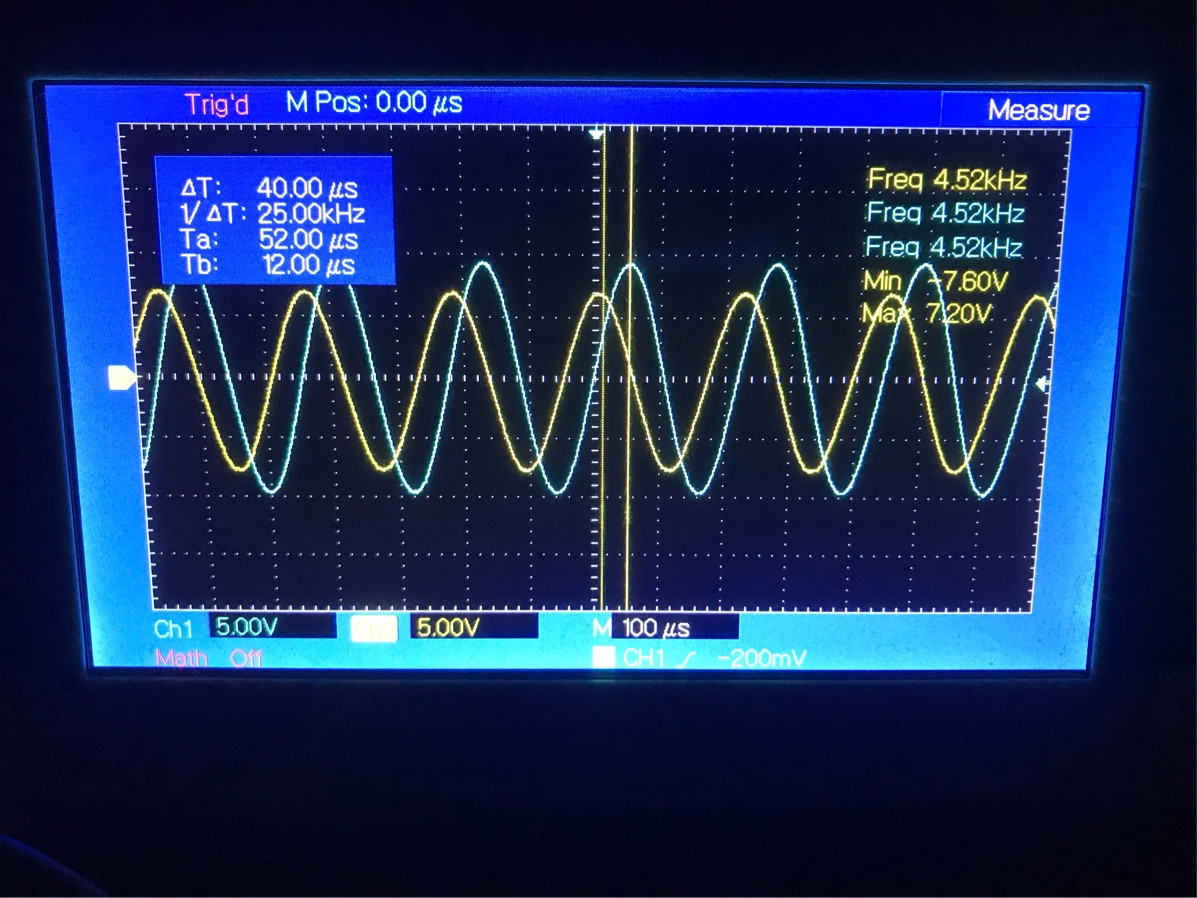
See the attached image. The maximum occurs at approximately 4.5kHz. The blue wave on the oscilloscope is the output signal after the resistor in the circuit above. The yellow the input signal. At 4.5kHz however, the waves are out of phase. Aren’t they supposed to be in phase?

EDIT1: As the frequency decreases below 4.5kHz, they get in phase. Above they get even more out of phase.

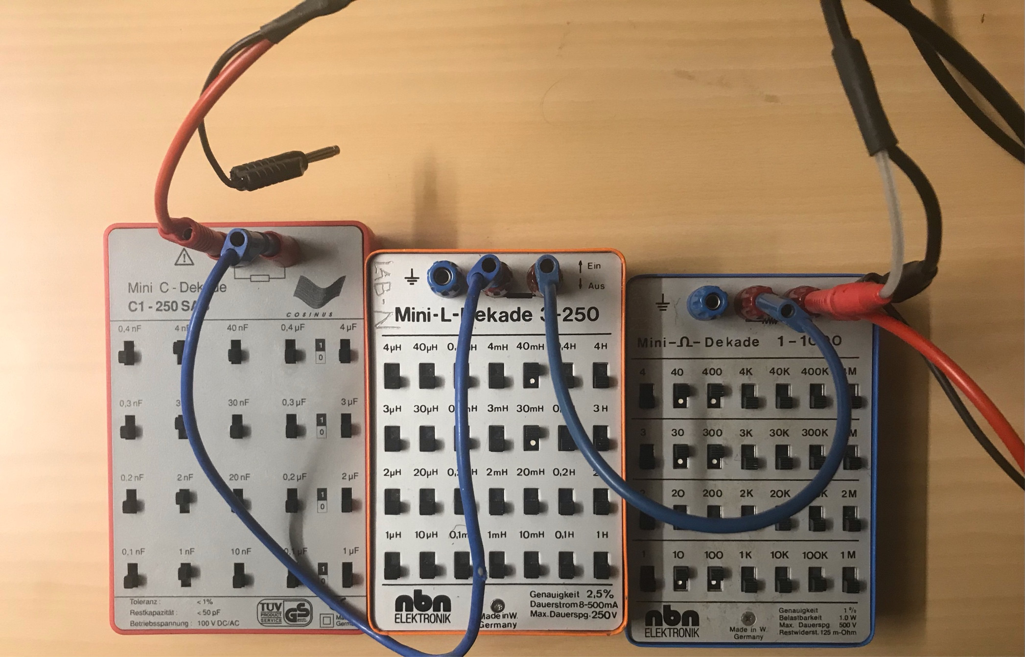
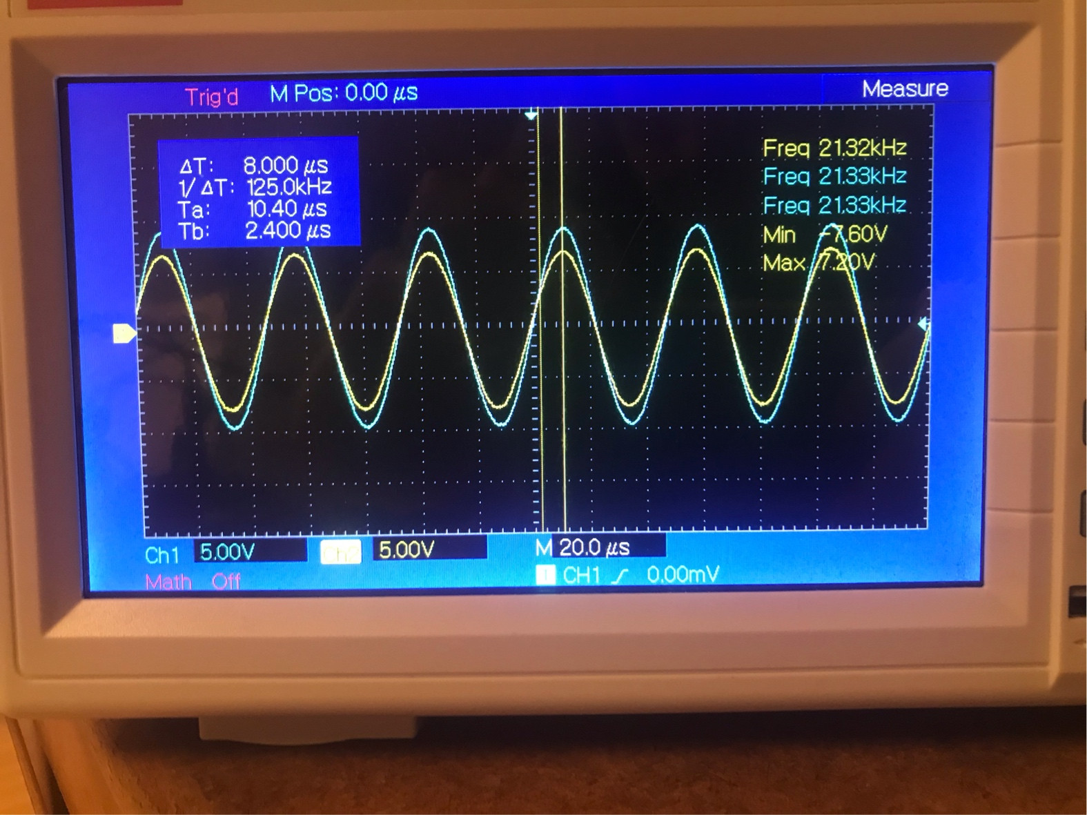
EDIT2: After increasing capacitor by 100 and decreasing resistor and inductor by 100, the two signals are more or less the same as the frequency varies.

\$\endgroup\$
11
  • \$\begingroup\$ Is the 4.5kHz resonant frequency calculated, or measured? \$\endgroup\$ Commented Jan 2, 2021 at 18:51
  • \$\begingroup\$ It’s supposed to be 5kHz according to the components chosen, but the amplitude of the blue signal peaks at 4.5kHz approximately. \$\endgroup\$
    – psie
    Commented Jan 2, 2021 at 18:53
  • \$\begingroup\$ Your resistor is quite high, and I am wondering whether it is interacting with the probe resistance on your oscilloscope. Can you test with a 10x probe, to see if anything changes? \$\endgroup\$ Commented Jan 2, 2021 at 18:55
  • \$\begingroup\$ What is a 10x probe? :) \$\endgroup\$
    – psie
    Commented Jan 2, 2021 at 18:58
  • \$\begingroup\$ It is typically used for measuring higher voltages. Oscilloscopes typically have a 1M\$\Omega\$ and 20pF input impedance. This impedance is added to your circuit. A 10x probe typically increases the input resistance to 10M\$\Omega\$. \$\endgroup\$ Commented Jan 2, 2021 at 19:03

1 Answer 1

1
\$\begingroup\$
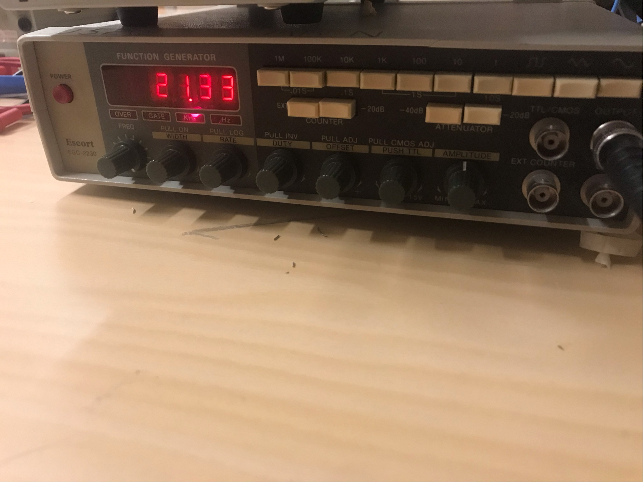
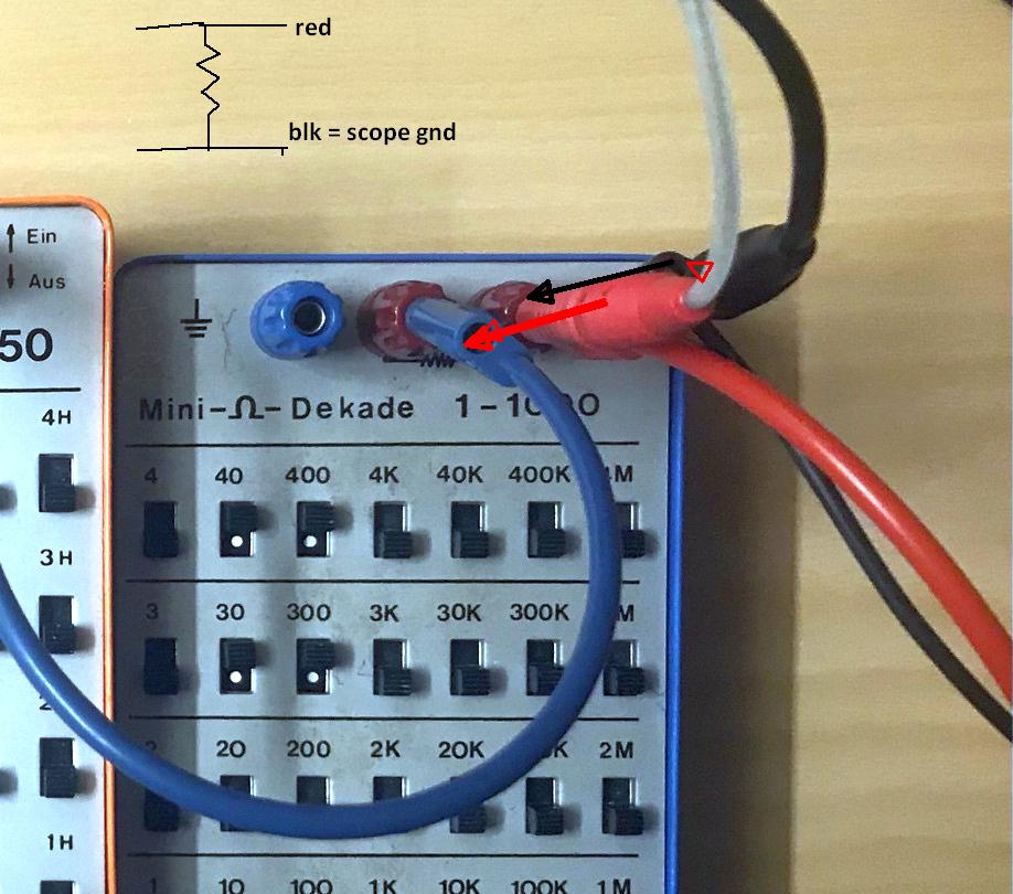
  • your scope probe for series current resonance must be in parallel of R and not in series with scope =1M

    • choose your load regardless of filter specs.

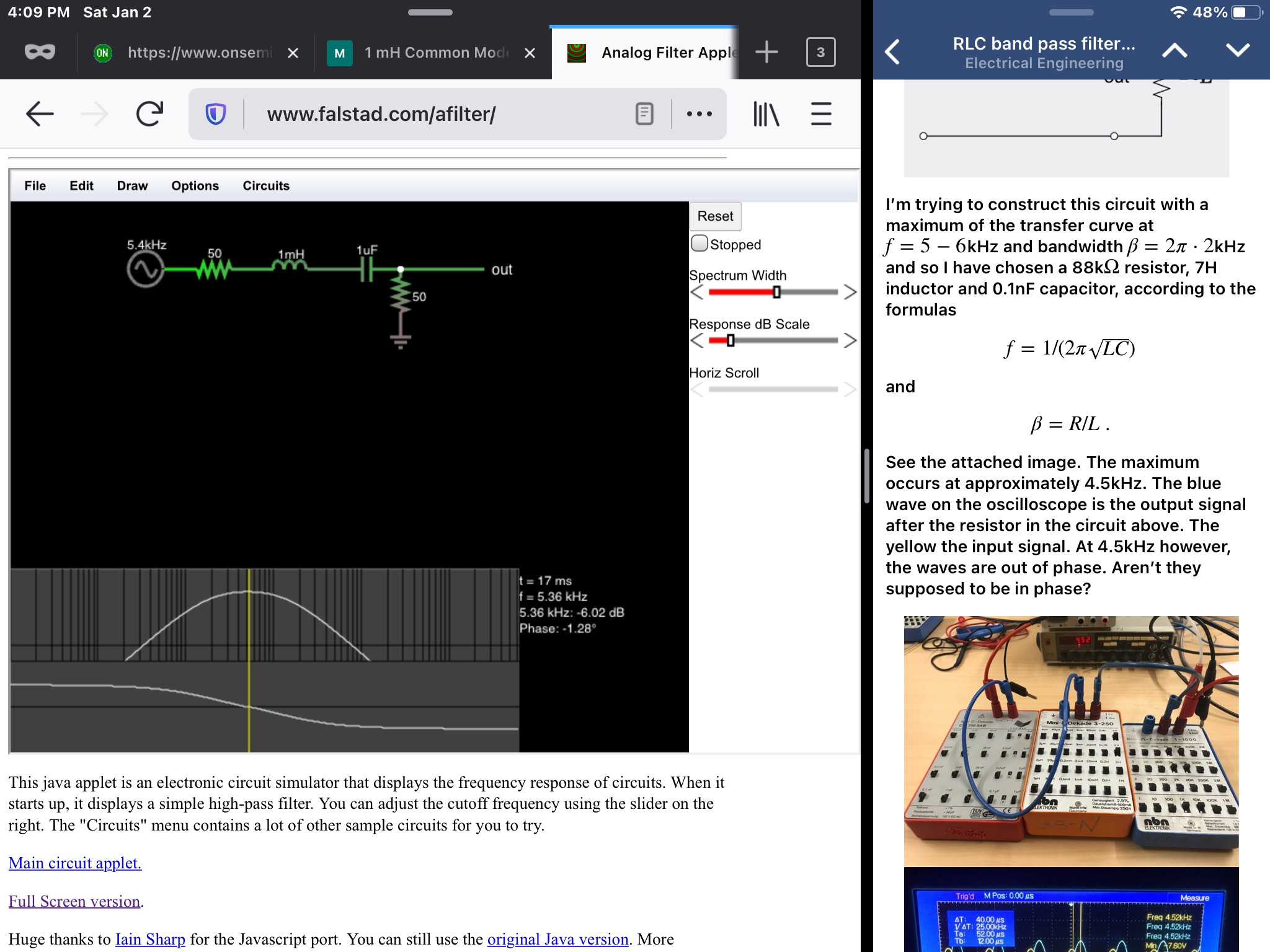
Here I chose 50 Ohms enter image description here

Move the scope probes as shown below. enter image description here

\$\endgroup\$
8
  • \$\begingroup\$ Do you know why he does not seem to be getting a peak in his response when he uses 10nF, 70mH and 880\$\Omega\$? \$\endgroup\$ Commented Jan 2, 2021 at 23:23
  • \$\begingroup\$ 70mH= 2639 ohms / 880 = Q=3. Yes his scope probe is in series with R instead of parallel \$\endgroup\$
    – D.A.S.
    Commented Jan 3, 2021 at 0:34
  • \$\begingroup\$ It works in the simulator. The question is why is he getting a flat response at least as far out as 21kHz, according to his reports. That is more than 3 times his resonant frequency of 6.02kHz. \$\endgroup\$ Commented Jan 3, 2021 at 0:38
  • \$\begingroup\$ That would indicate one of his two components is more than 10 times smaller than it should be, where Z is 12x larger and Q is 12x smaller than 3 or 0.25 =Q overdamped but the main problem is the scope connection \$\endgroup\$
    – D.A.S.
    Commented Jan 3, 2021 at 0:42
  • \$\begingroup\$ Are you suggesting I should connect the cable going into the resistor (the blue box) differently? One part consists of the signal generator the other from the oscilloscope. If so, how should I connect the oscilloscope cable? \$\endgroup\$
    – psie
    Commented Jan 7, 2021 at 18:27

Your Answer

By clicking “Post Your Answer”, you agree to our terms of service and acknowledge you have read our privacy policy.

Not the answer you're looking for? Browse other questions tagged or ask your own question.