0
\$\begingroup\$

I am designing a circuit board that will sit in an enclosure that will eventually sit in a garage to control a dust collector via an external relay. I have designed the PCB and I just wanted to make sure I have considered all the safety concerns when it comes to AC to PCB board that humans interact with using push buttons.

PLEASE PLEASE BE AS CRITICAL AS YOU COULD!!

Some info:

  • AC input will only need to handle a max of 3 Amps (Trace Width is currently 60 mils external)
  • The MCU is an ESP32 DevKitC module
  • The 433MHz Receiver is a basic breakout board (433Mhz Rf Transmitter and Receiver Module Board Link Kit)
  • AC line inputs are coming in with a wire-screw to board connector.
  • The AC/DC converter is a RAC03-05SK which converts from AC (85VAC-265VAC)

Concerns:

  • How do I protect our kind human when they are interacting with the module (say pressing a button) and to ensure no AC wondering current just flow through them. I have access to the Earth but I am unsure what I should do with it or where to connect it.
  • Is my DC ground bottom pour good enough?
  • Since this device is going to be in a garage I am sure dust will be involved. Is there anything that I need to be worried about when designing for a place that has pollution and if so what kind of worry should I have?
  • Do I need any fuses?

I know this might be a very simple design but I just become concerned when it involves AC. DC I am not too worried. Any suggestions, recommendations and any critiques are much much MUCH appreciated!

Thank you so much in advance.

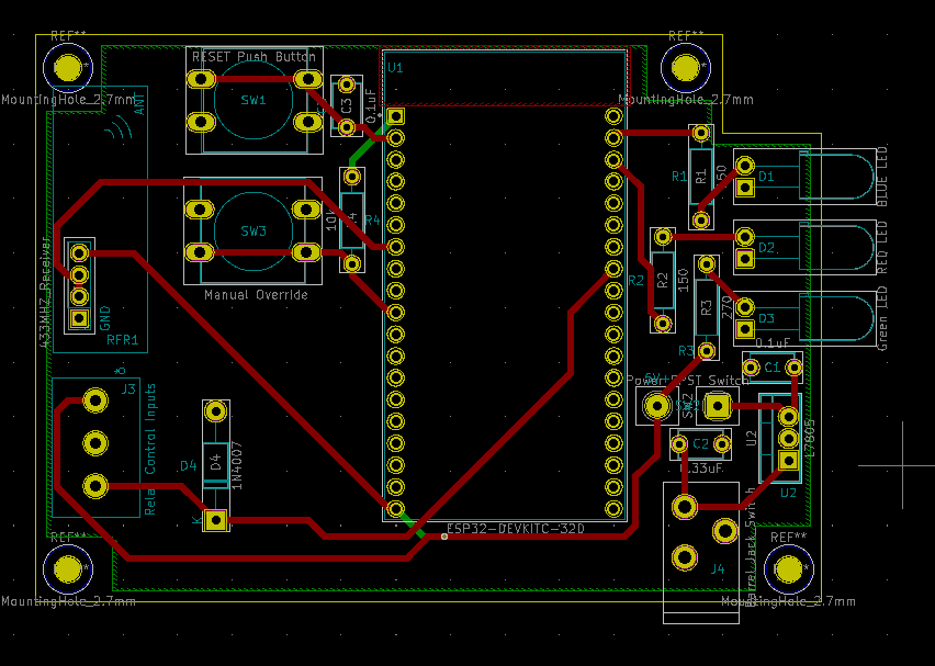
Here is a picture of the PCB design with the ground pours shown: enter image description here
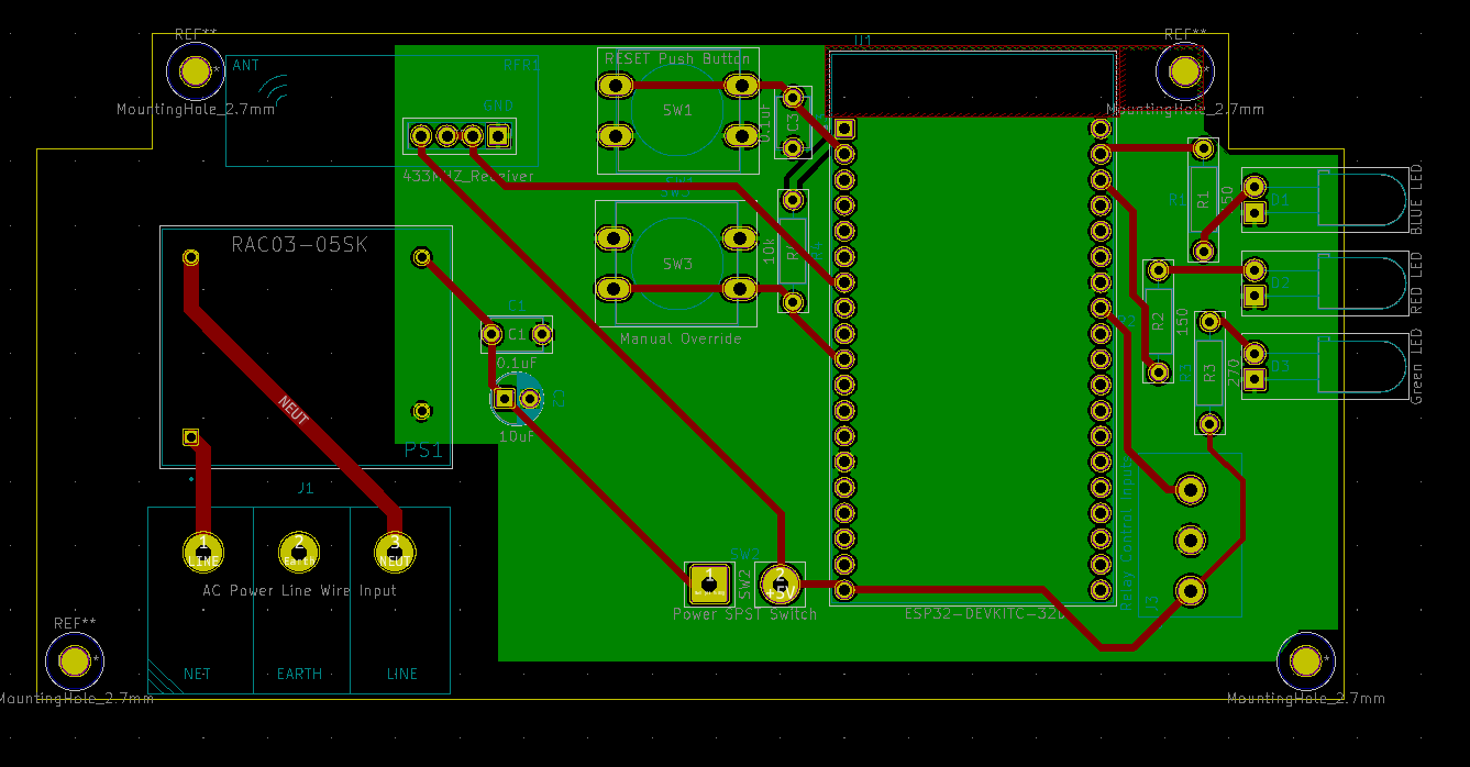
Here is a picture of the PCB design without the ground pours shown: enter image description here
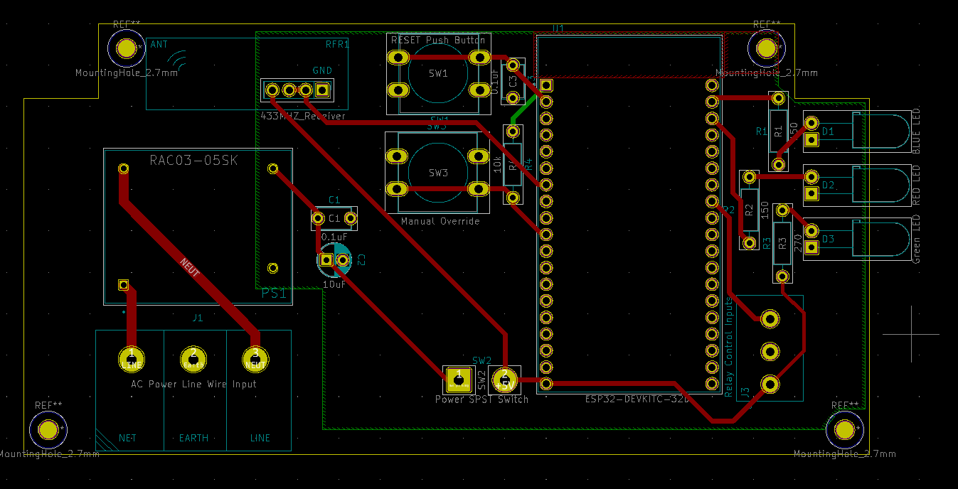
The overall schematic: enter image description here

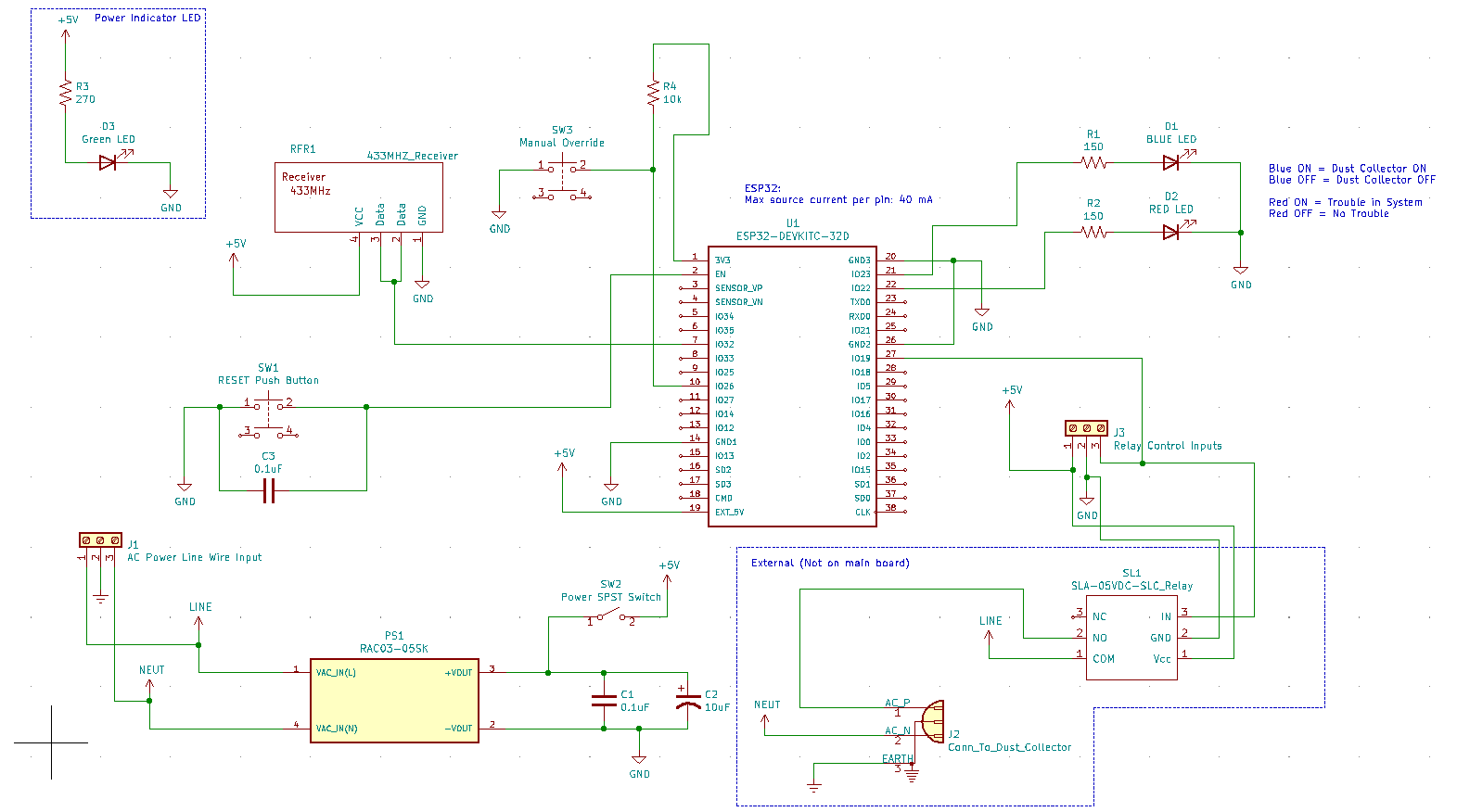
EDITs for anyone that might find this helpful! Please review the answers for details:

enter image description here

Removed the AC part of the circuit and just moved it to a wallwart which is much safer and less liability! Thanks @Kyle B for your help!

\$\endgroup\$
0

1 Answer 1

3
\$\begingroup\$

Is this intended to be mass-produced and sold to consumers????

EDIT: Instead of adding fuses... since this is a one off build and won't be subject to professional testing.. please drop the AC high voltage off this board completely. You can make a truly safe design using a common wall adaptor. As a bonus, since power supplies are a common failure point, you make it way easier for future repairs to be done.

If this causes a fire because it's a home-made thing hooked directly to AC main, an insurance company may not pay out. And you may be liable if somebody gets hurt.

As a bonus, it also will remove your concern about "what to do with Earth ground"!

END EDIT

The trace leading to pin #2 on U1 is very very close to Pin #1. I would move that.

Move the ground pour away from your standoffs. You could potentially get a short from a screw-head. –

Make the pads on the bridge rectifier much larger. Those are gonna be hard to take solder,and even harder to repair if you have to replace it.

Having a metal standoff screw so close to your antenna might cause problems with it's function.

Where's your fuse? You absolutely should not use line voltage without protection.

It would be a very good idea to have a flyback diode across the relay coil to prevent voltage spikes from getting back into your board and zapping something.

Are you sure the two data lines on your radio module are supposed to be connected together??? Usually you'd have an INPUT and an OUTPUT line.

Suggestion: Use "diffuse" LED's, not clear ones. Diffuse LED's are better for indicator lights. Clear LED's are for when you want to project light to another surface.

Another suggestion: Print your PCB layout on paper at 1:1 scale, then lay all your components on it and make sure they fit right.

\$\endgroup\$
7
  • \$\begingroup\$ Thank you so much for the review I really appreciate it! As far as if it is intended to be sold to consumers and the answer is no not at all. This is for just one person that needed it custom made specific for them. I just needed it to be a clean and nice design and therefore I made the PCB design. I will make the suggested edits. I will also need to add the fuses as well. Thank you so much! \$\endgroup\$
    – AhmedB
    Commented Feb 4, 2021 at 1:25
  • \$\begingroup\$ Instead of adding fuses... since this is a one off build and won't be subject to professional testing.. please drop the AC high voltage off this board completely. You can make a truly safe design using a common wall adaptor. As a bonus, since power supplies are a common failure point, you make it way easier for future repairs to be done. \$\endgroup\$
    – Kyle B
    Commented Feb 4, 2021 at 4:56
  • \$\begingroup\$ @KyleB that's important enough to be worth adding to your answer. \$\endgroup\$
    – K H
    Commented Feb 4, 2021 at 5:19
  • \$\begingroup\$ @KH You're right \$\endgroup\$
    – Kyle B
    Commented Feb 4, 2021 at 5:29
  • \$\begingroup\$ @KyleB you are absolutely correct! I love this answer so much and it makes so much sense to be protected. As I have been so worried about that fact. I will add just a simple barrel plug and call it a day (safe day!). But what do you recommend to do about the relay? Keep as is where the ac power goes into the relay? Then goes out to the dust collector? That should be fine right? \$\endgroup\$
    – AhmedB
    Commented Feb 4, 2021 at 15:10

Your Answer

By clicking “Post Your Answer”, you agree to our terms of service and acknowledge you have read our privacy policy.

Not the answer you're looking for? Browse other questions tagged or ask your own question.