I have an arc lighter similar to this one:
The switch failed after a couple days (typical Chinese garbage), so I took the unit apart to replace it. Also, due to its operating frequency (~16Khz), it makes an appalling screeching sound that hurts my ears. So while I had it open, I decided I would attempt to modify it for a higher frequency.
By photographing both sides of the PCB; by using a multimeter; and by shining a light through the board, I managed to reverse-engineer it. Mostly.
My initial intention was to leave the micro in place, but insert a 555 timer between the chip and the MOSFET that drove the output coil. Its reset line would be asserted high by the chip's square wave output (by way of a diode, a resistor and a capacitor), and it would output a (thankfully inaudible) 22KHz signal to the MOSFET.¹ So far, so good.
My initial tests were promising, but in the end a pin broke off the chip and necessitated its replacement. Onto plan B then.
I figure I can just replace the (now defunct) chip with another microcontroller (specifically, a PIC or Atmel one), and write some firmware to perform the original functions, albeit at a higher frequency.
The microcontroller is unmarked, but fortuitously I have other microcontrollers with a compatible pinout. There is a problem, however. I don't understand the purpose of one of the connections on the board!
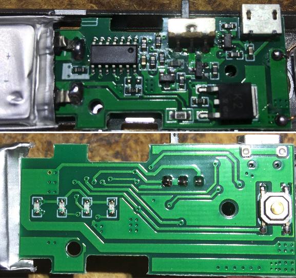
Here are the photographs I worked from. The high voltage transformer connects at the far right, and the 3.7V lithium battery at the left.² The lower image is flipped for convenience.
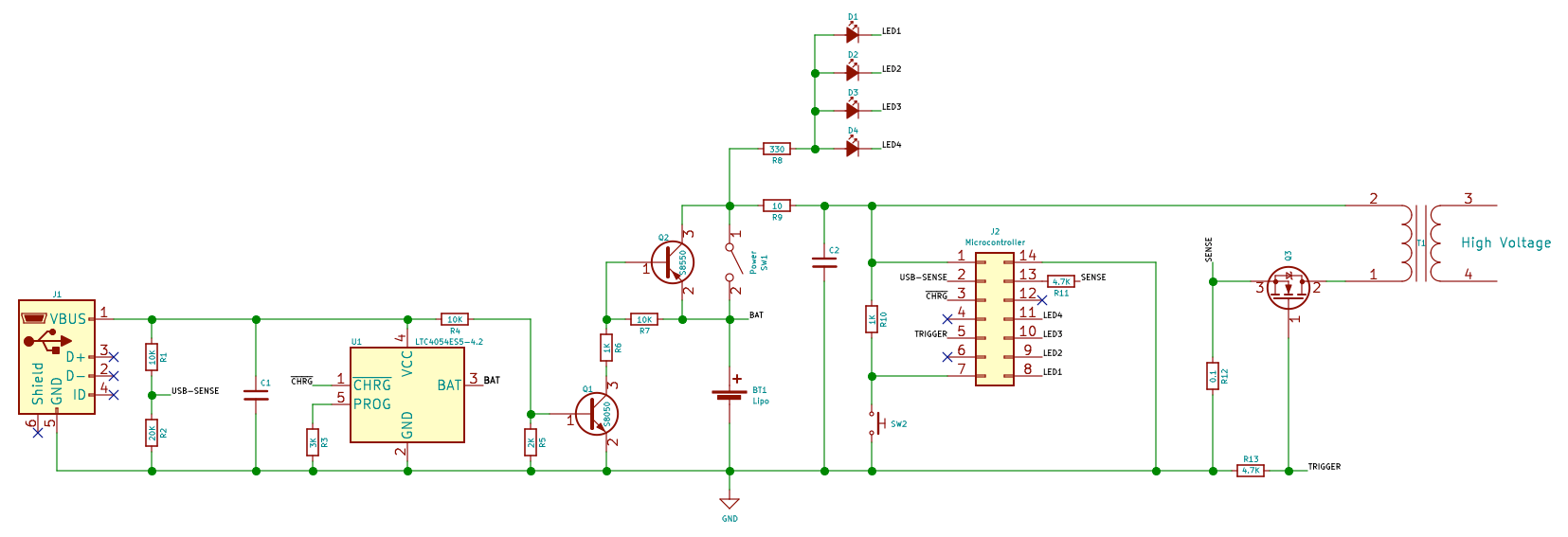
From those pictures, I derived the following schematic:
My understanding of the circuit is as follows:
- The LTC chip is responsible for charging the battery.
- Voltage on the USB connector bypasses the power switch by way of Q1 and Q2, activating the microcontroller, in order that the charging lights may illuminate in sequence.
- The microcontroller monitors the USB voltage on pin 2, and refuses to trigger if a voltage is sensed.
- Pin 3 is for detecting when the battery is fully charged, in order to display the LEDs statically lit to indicate charging is complete.
- Pin 5 is the output pin, by which the chip outputs a 60% duty-cycle 15Khz square wave³ to the transformer via a MOSFET.
So, my question is...
- What is the purpose of the current sense resistor R12 (measured by pin 13)?
I have no way to know the model of microcontroller used in this product, or the internal workings of its firmware. So, what can be deduced from the circuit, in terms of how pin 13 is likely to affect the microcontroller's behaviour?
EDIT: I notice there is no back-EMF clamp diode on the transformer. Should there be?
¹ Unfortunately, I discovered that the 555 drives its output low when reset is low; driving the MOSFET on continuously, except when the square wave was present. There was some smoke, and the MOSFET physically desoldered itself from the board! Fortunately I was paying attention and disconnected it immediately; and I'm pretty sure no permanent harm was done. I added an NPN transistor and the problem went away.
² Yes, those dents happened during disassembly. Oops.
³ I measured this with an oscilloscope.


