Let's fix a few other things first.

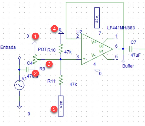
Figure 1.
- GND symbols should point down to the ground, not to the sky. The upward arrow is often used to signify connection to VCC so it risks confusion.
- You've AC decoupled in the wrong place move C2 from here to (3).
- As wired here the pot is pulling your VCC/2 reference to ground. Consider what happens when you move the wiper to the top of the pot.
- Swap R10 and R11 and your VCC and GND will be the right way up with higher voltages higher on the page and current flowing from top to bottom.
- See (4).
We'll also fix the pot orientation.

simulate this circuit – Schematic created using CircuitLab
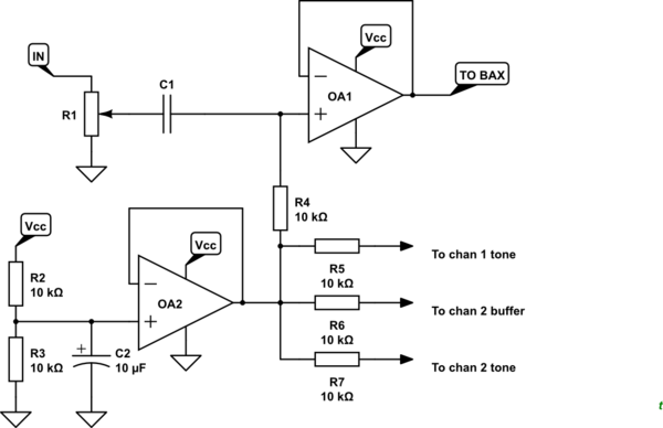
Figure 2. The modified circuit.
- The pot is the right way up. Moving the wiper up will raise the volume.
- The pot GND (and all the others) are pointing down.
- C1 is positioned after the volume control wiper. This prevents the pot wiper affecting the non-inverting bias.
- If you're worried about DC coming in on the audio signal you can add another capacitor on the input.
- OA2 provides a "stiff" buffer for the VCC/2 mid-rail supply. C2 keeps the voltage steady even if VCC has some noise on it.
- R4, 5, 6 & 7 provide the bias to the other four op-amps. OA2's output is stable and low impedance so the audio signals on the other op-amps don't interfere. I realise I've set these resistors to 10k which may load the audio signal a bit too much. 100k or more should be fine.
If you're interested in developing your skills have a read of Rules and guidelines for drawing good schematics.
Have fun!
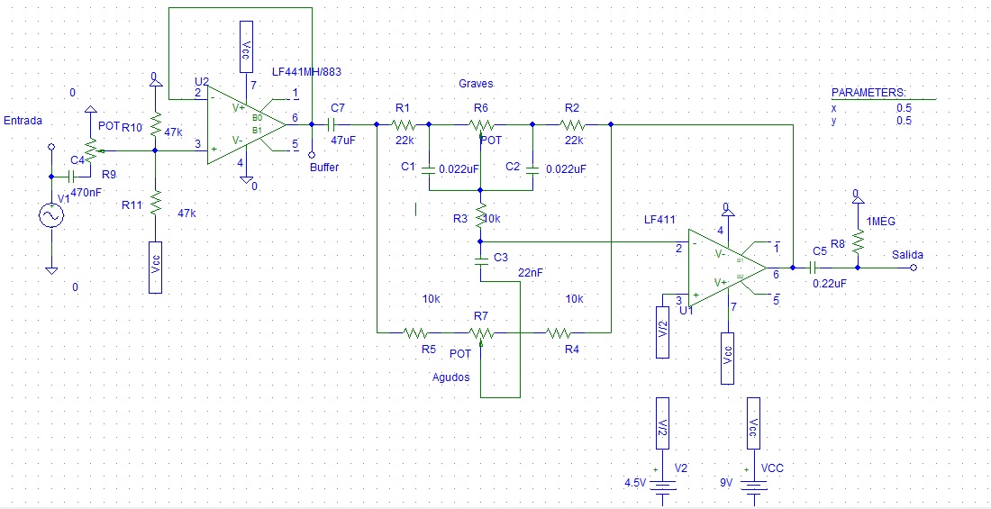
 Im building a Stereo Buffer and a Baxandall circuit together. In powering the circuit with a single supply of 9v, and i need to bias each four inputs with 4.5 volts. The question is: If i feed the four inputs with the same reference voltage line will a have problems with the signals that are different. Into the buffer the signal is the IN signal, but in the Baxandall input the signal is the output buffer. But if i used the same voltage reference i suposed that im going to have a mix of both inputs signals in the baxandall, im right? How i can fixed that thing?

