0
\$\begingroup\$

Consider the RLC circuit below. enter image description here
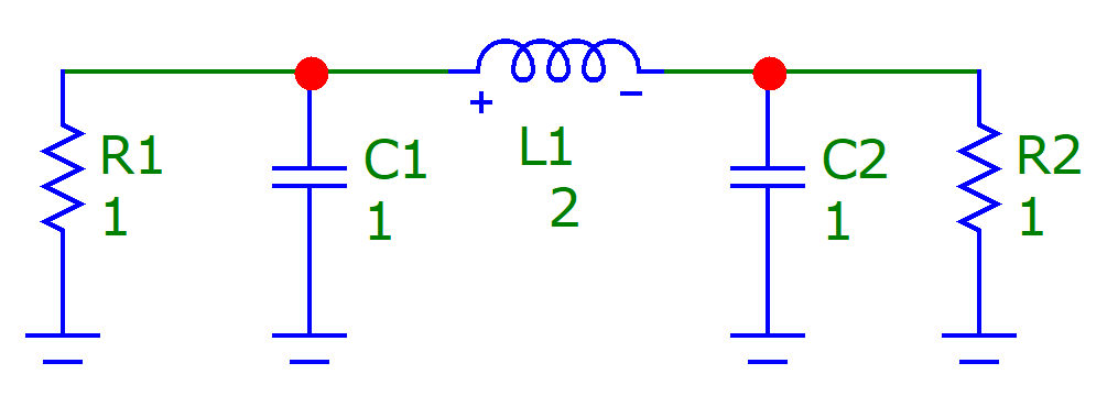
In fact, it is a normalized filter with Butterworth approximation of 3rd order.

Now suppose that for some reason I am interested in the time domain formulation. Using KCL and KVL I ended up with these state equations:

\begin{gather} \frac{\mathrm{d}i_L}{\mathrm{d}t} = \frac{1}{L}(v_{C1} - v_{C2})\\ \frac{\mathrm{d}v_{C1}}{\mathrm{d}t} = \frac{1}{C_1}\left(\frac{v_{C1}}{R1} + i_L\right)\\ \frac{\mathrm{d}v_{C2}}{\mathrm{d}t} = \frac{1}{C_2}\left(\frac{v_{C2}}{R2} - i_L\right) \end{gather}

But when I am trying to get a transient response of these equations using some numerical integration scheme like Runge-Kutta or implicit backward Euler, the solution blows up.

Only for an initial condition \$(0,0,0)\$ it is zero everywhere. Whenever I try to put the different initial conditions, let's say \$(0.5,1,1)\$ it blows up.

Am I using initial conditions the wrong way? How to choose them correctly? I understand that by saying that for example \$v_{C1} = 10\$, it means that \$i_L = 10/(1||1)\$. Or is it even true? What is then \$v_{C2}\$?

\$\endgroup\$
4
  • 1
    \$\begingroup\$ Simulate it in spice or some other transient package \$\endgroup\$ Commented Jun 4, 2021 at 12:34
  • \$\begingroup\$ The initial voltages on caps and currents through inductors are independent of each other. \$\endgroup\$
    – ErikR
    Commented Jun 4, 2021 at 12:57
  • \$\begingroup\$ which means that my equations are wrong but I cant see it. it is probably messing with this single current \$\endgroup\$
    – struct
    Commented Jun 4, 2021 at 13:00
  • 1
    \$\begingroup\$ When you say blow uo, please explain with a waveform. Zoom into the waveform of the values go to ranges above, say, 10 V. \$\endgroup\$
    – AJN
    Commented Jun 4, 2021 at 14:35

1 Answer 1

2
\$\begingroup\$

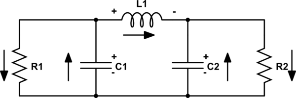
I think the problem might be that your cap currents don't follow your +/- convention.

Here I've drawn all of the +/- indicators and current arrows:

schematic

simulate this circuit – Schematic created using CircuitLab

The resulting KCL and KVL equations are:

$$ \begin{align} C_1\frac{dv_{C_1}}{dt} + \frac{v_{C_1}}{R_1} + i_L &= 0 \\ C_2\frac{dv_{C_2}}{dt} + \frac{v_{C_2}}{R_2} &= i_L \\ L\frac{di_L}{dt} &= v_{C_1} - v_{C_2} \\ \end{align} $$

Translating your equations back to KCL current equations I get: $$ \begin{align} i_{C_1} &= i_{R_1} + i_L \\ i_{C_2} &= i_{R_2} - i_L \\ \end{align} $$ which means the current arrows look like:

schematic

simulate this circuit

\$\endgroup\$
1
  • \$\begingroup\$ I made corrections according to your suggestions and now it works perfectly. Next time I must be more precise. Thank you, it helped me \$\endgroup\$
    – struct
    Commented Jun 5, 2021 at 18:47

Your Answer

By clicking “Post Your Answer”, you agree to our terms of service and acknowledge you have read our privacy policy.

Not the answer you're looking for? Browse other questions tagged or ask your own question.