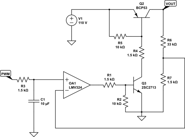
I made a project with the objective of changing the supply voltage of a system (VOUT in the circuit) through a PWM signal.
The initial objective was to vary the supply voltage of a secondary circuit (bridge H) from 0V to 110V continuous.
I thought of doing this using a system with an op amp. I put an RC circuit on the amplifier input to convert the PWM signal into an analog signal. My intention was as follows: 50% duty = 55V at the output; 100% duty = 110V (approximate considering drops) at the output.
But what I have in VOUT is a pulsing signal with amplitude of 120V and RMS voltage varying (that wasn't my intention).
can anybody help me?

simulate this circuit – Schematic created using CircuitLab
EDIT 1:
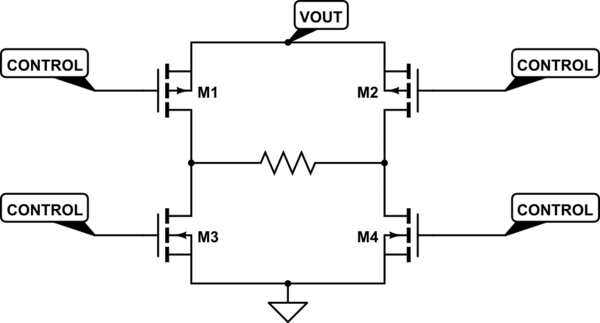
The VOUT load will be an H-bridge. Similar to the circuit below:

