0
\$\begingroup\$

I am currently trying to learn more about video signals. I'm particularly interested in NTSC since I live in North America.

I recently bought an oscilloscope (Siglent SDS1104X-E) and I am trying to look at the composite NTSC signal output by a Playstation 1 (SCPH-101/PSone/NTSC-U/C).

Now I was happy to learn that my scope had a NTSC trigger built in, however I couldn't get it to trigger at all in this mode...

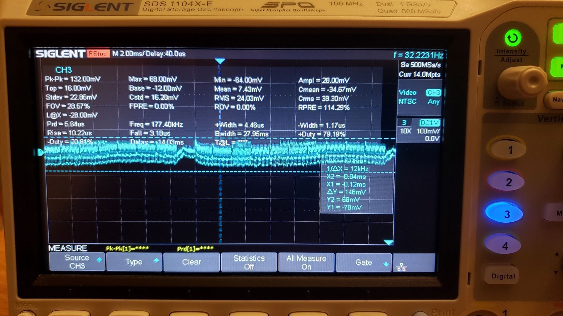
Anyway I forced a trigger and this is what I got:

enter image description here

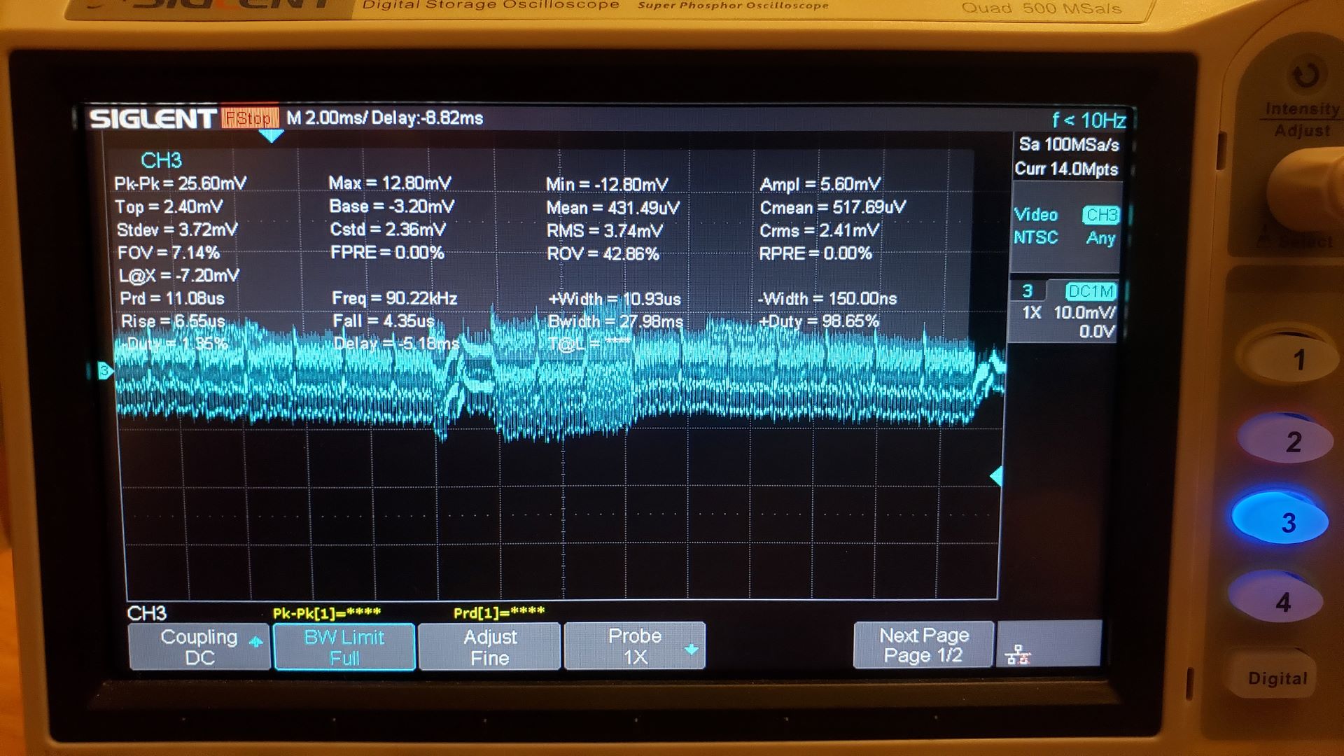
From what I've read on NTSC the reference white should be 100 IRE (714mV) in amplitude and the sync level should be -40 IRE (-285.7mV) in amplitude so I don't understand how come my scope calculate a minimum amplitude of -12.80mV? Shouldn't it be around -285.7mV? Is the playstation generating a scaled down signal somehow?

Here's a picture when I zoom in on the signal:

enter image description here

To me this looks like 1 scanline worth of signal. So I think the signal looks fine except for the amplitude. I can clearly see the signal dropping to the sync level followed by the color burst.

enter image description here

What am I missing here? Why is the signal amplitude wrong? How can my TV even display this signal correctly?

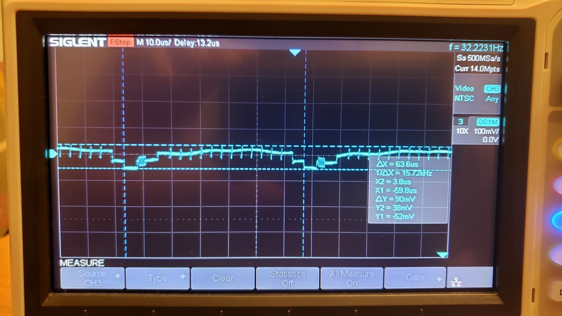
Edit 1: New picture with probe and scope @10x

enter image description here

enter image description here

I have the playstation with the tray opened so it's most likely displaying the bios screen:

enter image description here

Edit 2:

I don't have an "optimal" way to connect the probe to the component signal I had some RCA ports laying around but no pcb to solder them on. So I connected the RCA cable into this port and connected the probe directly to the pins.

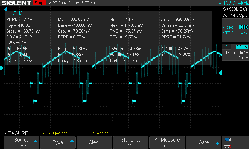
I tried connecting the probe directly to the end of the rca cable and I am getting a MUCH better signal, the NTSC trigger now works. However the amplitude seems too high. With sync level at about -1.14V, I also set the scope back to 1x otherwise I get -11.40V (that can't be right?)

enter image description here

Edit 3:

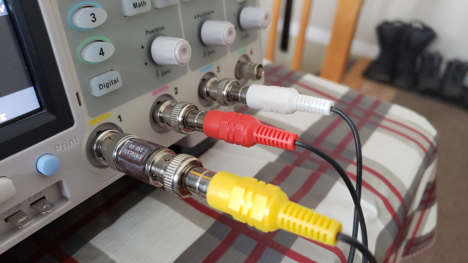
I am sorry it's been a while since I posted. I had another go at measuring NTSC signals recently but I bought some more equipment to do better testing. What I got was some RCA to BNC adapters and a 75 ohm plug-in BNC termination (as suggested in the answers). I set the probe setting to 1x on the scope and I got MUCH better amplitude readings.

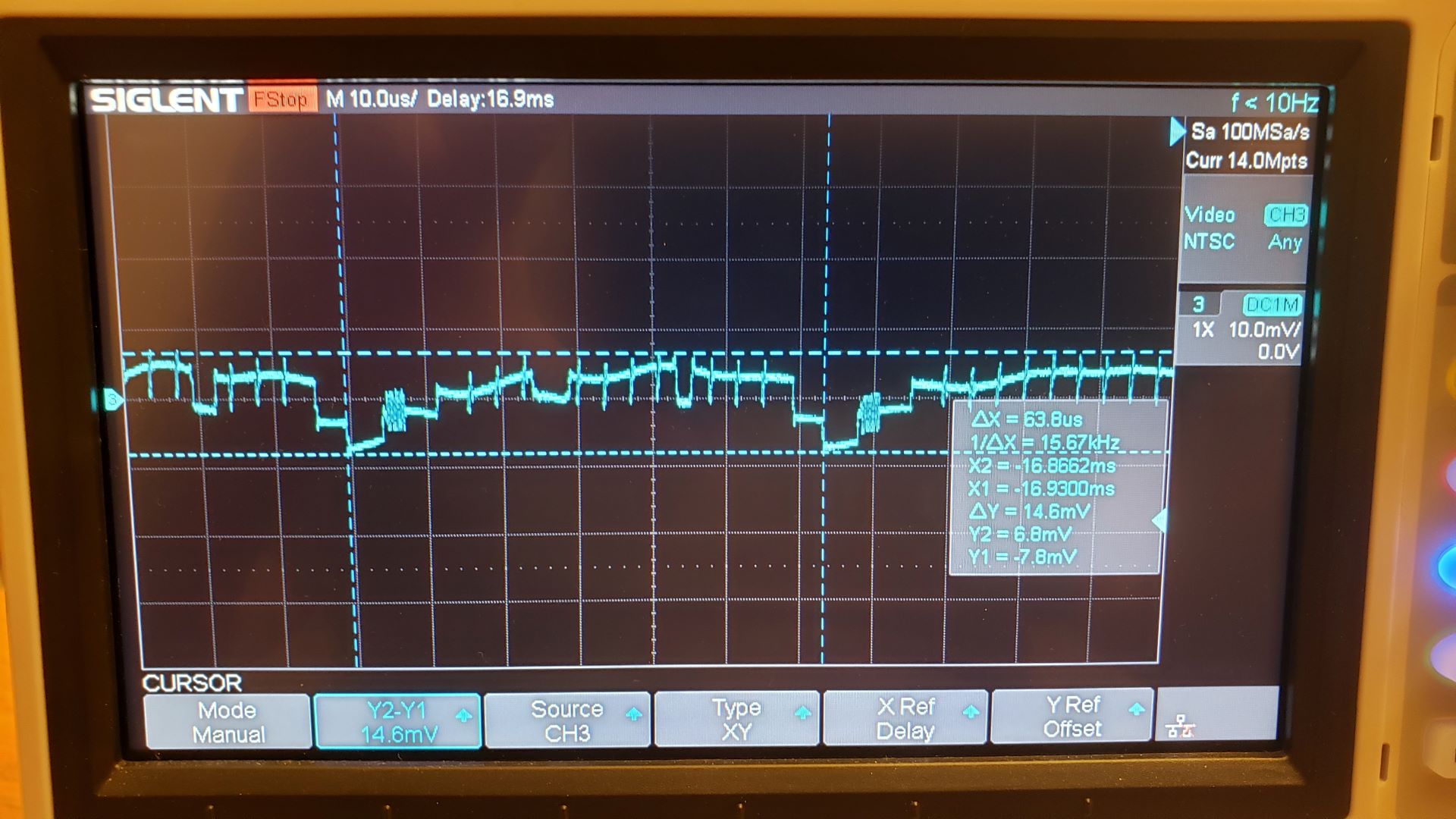
enter image description here

enter image description here

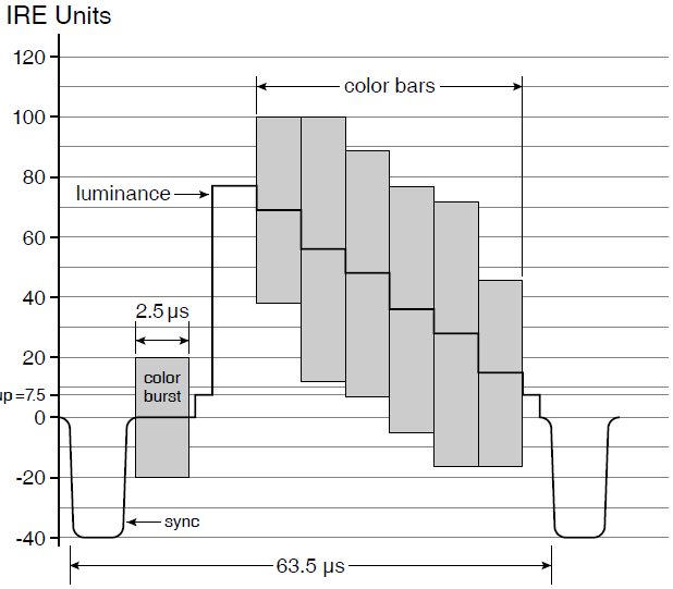
Now to compare my new measurements to the standard:

enter image description here

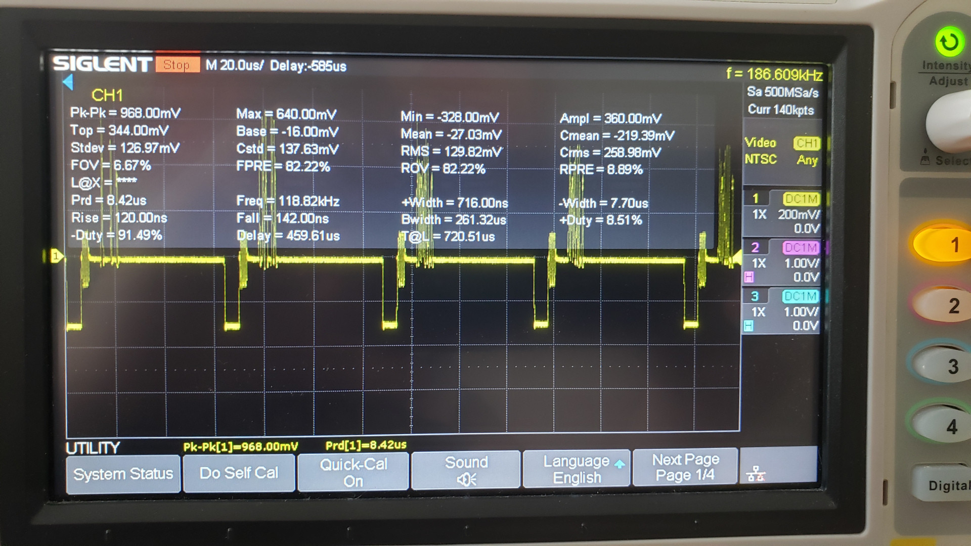
I now have a peak to peak amplitude of 968 mV which is pretty close to the 1V p-p amplitude defined in the NTSC standard (~4.5 IRE difference but depends if the signal contain any luminance at peak white level). The sync level is slightly off, I get -328 mV and the standard should be -285.7 mV for a total of 42.3 mV difference or more or less 6 IRE. The color burst amplitude is also slightly off, I get about 116 mV and the standard is 142.86 for a difference of 26.86 mV or about 4 IRE. Does anybody know if this is an acceptable error margin or is there any way I can go about improving my measurements?

\$\endgroup\$
16
  • \$\begingroup\$ What's being displayed on the screen at the moment? If it's very dark, the amplitude will be low. There's no fixed amplitude; the only fixed amplitudes are those of the sync pulse and the color burst. \$\endgroup\$
    – Hearth
    Commented Jun 13, 2021 at 3:34
  • \$\begingroup\$ You also are probably using a 10X probe, but the scope is set to 1X. \$\endgroup\$
    – Hearth
    Commented Jun 13, 2021 at 3:35
  • \$\begingroup\$ oh thanks for pointing that out I took some new pictures with both the probe and scope set to 10x. However it doesn't change the fact that -52mV measured level for the sync level is far from the -285mV its supposed to be? \$\endgroup\$
    – Lexx32117
    Commented Jun 13, 2021 at 3:54
  • \$\begingroup\$ With the probe "set to" 10x? If you have one of those switchable probes, get rid of it and get a proper 10X probe, those switchable ones are garbage. Not enough so to be causing this though--I suspect something may be loading the signal too much, or you may be at the limits of your probe's or scope's bandwidth. \$\endgroup\$
    – Hearth
    Commented Jun 13, 2021 at 4:01
  • 1
    \$\begingroup\$ You could also use the oscilloscope's built-in termination, though most scopes can only do 50 Ω termination as that's more common outside of video. Some scopes can do 75 Ω, though. \$\endgroup\$
    – Hearth
    Commented Jun 13, 2021 at 18:18

1 Answer 1

2
\$\begingroup\$

The signal is nominally 1.0 Vpp (140 IRE), but that is when it is properly terminated into 75 ohms resistance and only contains 100% white without color or 75% of color. If it has for example 100% bright yellow or cyan, the peak amplitude will be about 1.3 Vpp (about 171 IRE).

Without terminating it at all, the nominally 1 Vpp signal might be 2 Vpp. The correct way to terminate is to connect a 75 ohm resistor from the video signal pin to ground.

The last scope picture shows the sync amplitude is about 570mV, which is spot-on for a signal with double amplitude due to missing termination.

And notice that Vpp only means the signal amplitude, the DC offset can be literally anything between equipment, and they can be AC coupled so there is no fixed DC offset as it depends on the signal.

The composite signal would only be approximately 1Vpp, not exactly 1Vpp. Since it has 75 ohm source impedance, and terminated into 75 ohm impedance, obviously the tolerances and wire resistance etc can make the amplitude to have some tolerance. The tolerance can be quite large, as anyway the receiver such as TV has to have automatic gain control to either amplify or attenuate the signal to proper internal levels it uses. The receiver knows the proper signal level from the sync pulse amplitude.

And obviously both the probe and scope must be set to the same setting (x1 or x10), otherwise the scale of measurement is wrong. In practice, there is very little reason to use the 1x mode and 10x mode should be used by default.

\$\endgroup\$
2
  • \$\begingroup\$ Re your update: Looks quite normal. Consumer equipment has to tolerate some tolerance anyway. The input of TV likely has automatic gain control to normalize the levels. The sync pulse height is used as a reference for white and burst amplitude as reference for color. Unlikely the picture has peak white, and likely the composite video cable is not very good coaxial so it may have high frequency losses. \$\endgroup\$
    – Justme
    Commented Mar 18, 2022 at 20:01
  • \$\begingroup\$ It makes sense, the cables are just cheap 3rd party RCA cables and I read somewhere that it wasn't a good connector choice for an analog video signal. BNC would have been a much better choice and I believe it was used in professional video equipment at the time, for example in Sony's BVM RGB monitors. Nevertheless thanks for the answer the change in equipment and especially the 75 ohm terminator made a world of difference. \$\endgroup\$
    – Lexx32117
    Commented Mar 18, 2022 at 20:49

Your Answer

By clicking “Post Your Answer”, you agree to our terms of service and acknowledge you have read our privacy policy.

Not the answer you're looking for? Browse other questions tagged or ask your own question.