0
\$\begingroup\$

I am a high school student investigating how varying the current output affects the shape of the hysteresis curve of a transformer.

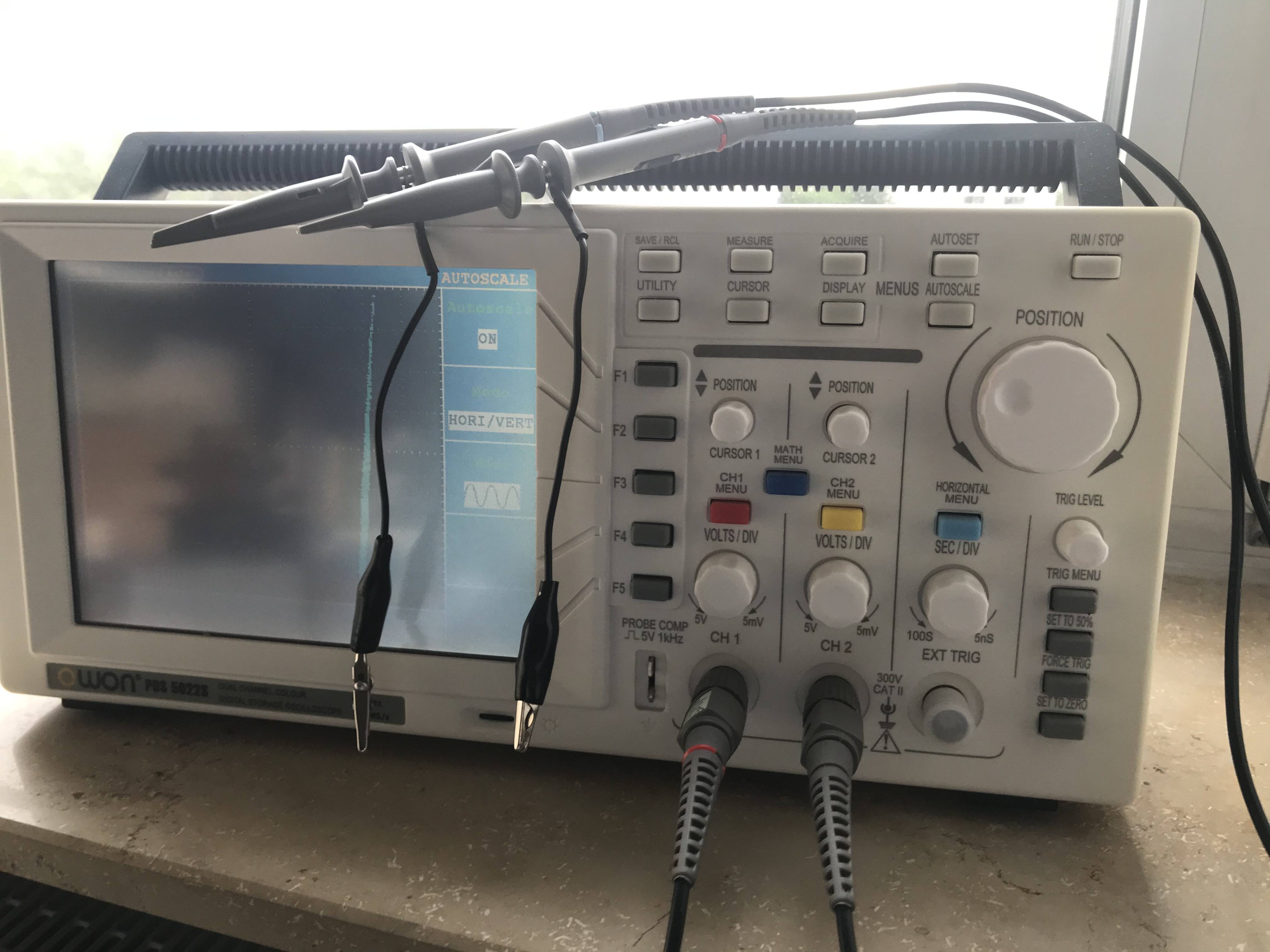
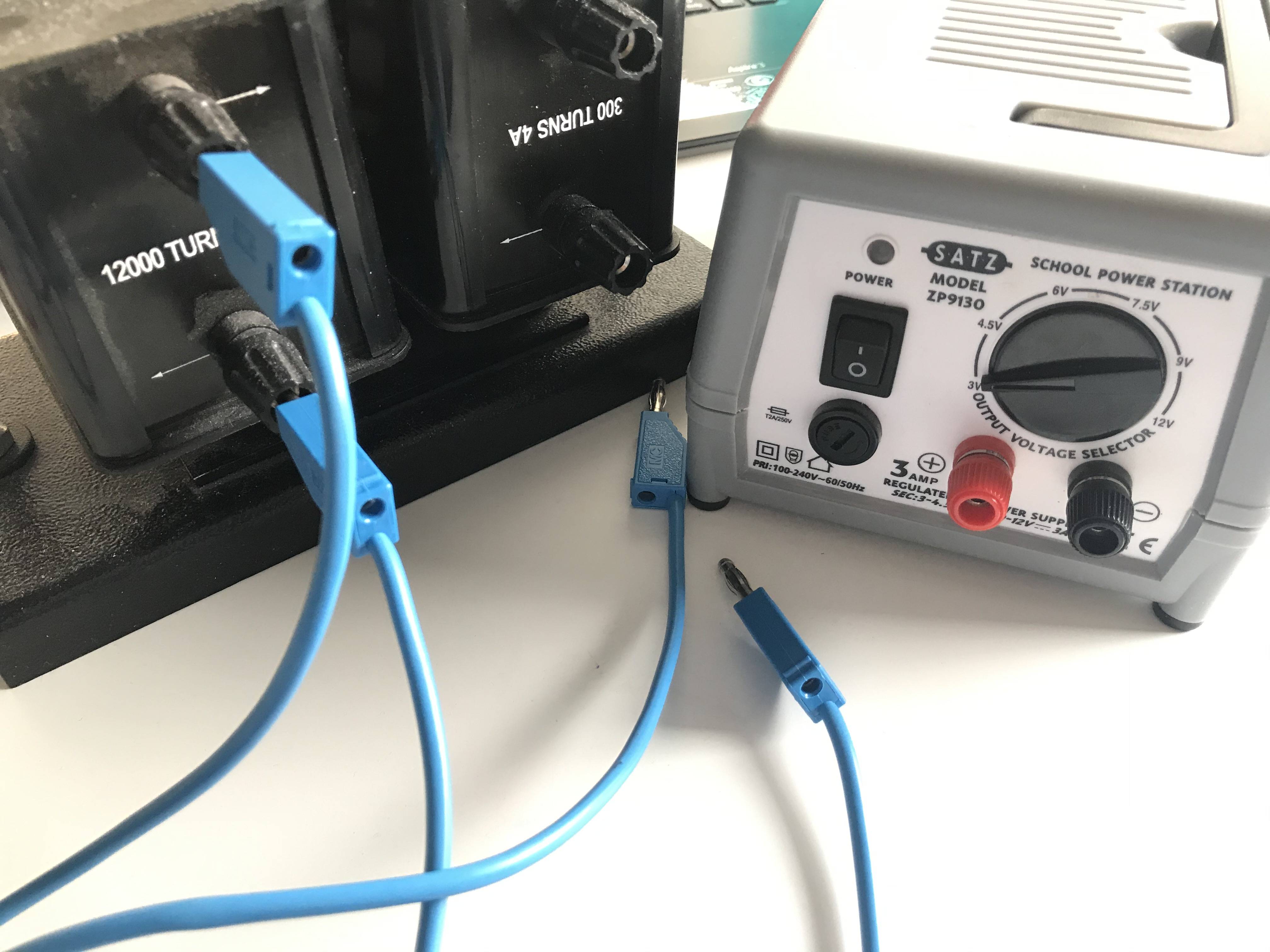
To measure the hysteresis curve of the transformer's core, I tried to connect my digital storage oscilloscope with a transformer of 10000 turns 0.05A. I also tried to connect them to my AC power supply. I plan to vary the AC current to see how it would affect the shape of the hysteresis curve's shape.

I am unsure about how to connect all three of them together.

The oscilloscope is already set in the XY mode.

Here is the equipment. Am I missing any necessary equipment? How should I set them up?

enter image description here enter image description here

\$\endgroup\$
5
  • \$\begingroup\$ What integrator are you using? \$\endgroup\$ Commented Jun 23, 2021 at 18:34
  • \$\begingroup\$ @aconcernedcitizen I am not sure what you mean, I am not using anything else other than the ones in the picture... \$\endgroup\$
    – Juye C
    Commented Jun 23, 2021 at 18:41
  • 1
    \$\begingroup\$ Have you seen this? You'll need to measure B and H and one of them requires integration. It might do you good to first read some more, otherwise not only you risk not knowing what you're looking at, but also what to search for. \$\endgroup\$ Commented Jun 23, 2021 at 18:53
  • \$\begingroup\$ A practical method of measuring hysteresis can be found in this article. \$\endgroup\$
    – qrk
    Commented Jun 24, 2021 at 1:03
  • \$\begingroup\$ @aconcernedcitizen I am using an RC integrator consisting 47mF of capacitor and 4.7k ohm resistor. I plan to measure and calculate the voltage output of the capacitor, which would be the Vout for the secondary coil in response to the primary one. This can give me the value for B. What would you recommend after this? \$\endgroup\$
    – Juye C
    Commented Jun 26, 2021 at 5:34

1 Answer 1

1
\$\begingroup\$

The SATZ ZP9130 power supply pictured is a DC power supply. You can't directly connect it to the transformer to measure the hysteresis curve - you need AC for that. You could use a simple two-transistor multivibrator circuit to produce the AC from DC, and feed it to the transformer. But that's probably not what you were meant to do. You need to ask for an AC supply for this experiment :)

Now, perhaps you can be manually flipping the current direction by reversing the plugs and observe hysteresis based on such transients alone. In theory - sure. But those power supplies are rather crappy, so:

  1. They can't really handle full current output for very long - their output stages overheat rather quickly.

  2. Disconnecting the inductance of the transformer primary winding while current flows in the circuit will generate high "kick-back" voltage, and is likely to destroy the output stage of the power supply.

    This will cause the pass transistor to fail shorted, i.e. it won't regulate anymore, and the output will be a DC voltage somewhere above 20V, and the voltage selector switch won't change it. You'll also lose the secondary overload protection in the supply that way, although it was lousy to begin with.

\$\endgroup\$

Your Answer

By clicking “Post Your Answer”, you agree to our terms of service and acknowledge you have read our privacy policy.

Not the answer you're looking for? Browse other questions tagged or ask your own question.