So quickly getting out of things I have previously done in trying to send SPI controller signals across long ranges using either 18 AWG cable or based on all the recommendations we have been reading, using two way MAX485 or RS232 transmit/receive with cat5/6 cable.
The initial phase 1 of our build is to stay with the SPI controllers for the LEDs and later on move to programmable so adding in Pi or Arduino based and removing the SPI controllers. We don’t want to do that for this phase if we can help it.
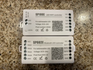
I’m using several different SPI LED controllers such as the btf lighting sp108e and 602e (pictured.) We also have 608es for music integration (trigger input into the SPI controller):
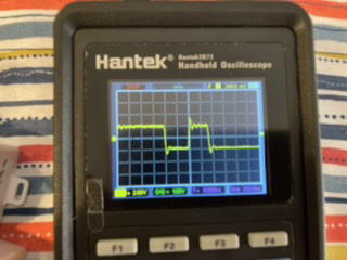
Which have an output signal of nominally 1.5 to 2 volts:
We want to use transmit/receive modules on both ends of the cable with direct input from the SPI controller to the transmit and the receive end terminates to an LED strip (WS2815.)
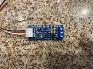
The modules would be something like these:
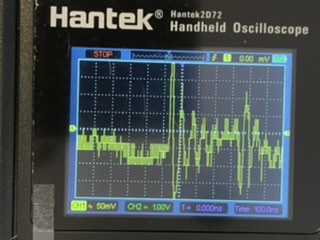
For the TTL to 485 conversion, when I hook up my circuit though my output to the LED side for the receive is no longer clean, and I’m looking at a 200mv output at a completely different waveform:
the 485 states it can only work with 3.3/5V data. Do I need to shift my SPI voltage data to one of those and what would be the best way to do that?
Will shifting the voltage affect the data phase? Will it also take care of the issue with the A and B transmission lines as right now I am not getting the inverse of A on the B line?
Do I need a terminator on the receiver side of this circuit? I have read that on a lot of these circuits you do.
I thought that this circuit would be more straight forward with the TTL output from the SPI controllers, but there is something being lost during the transmit/receive - my suspicion is the voltage trigger for the circuit but I really don’t understand this circuit well enough and looking for help.
UPDATE:
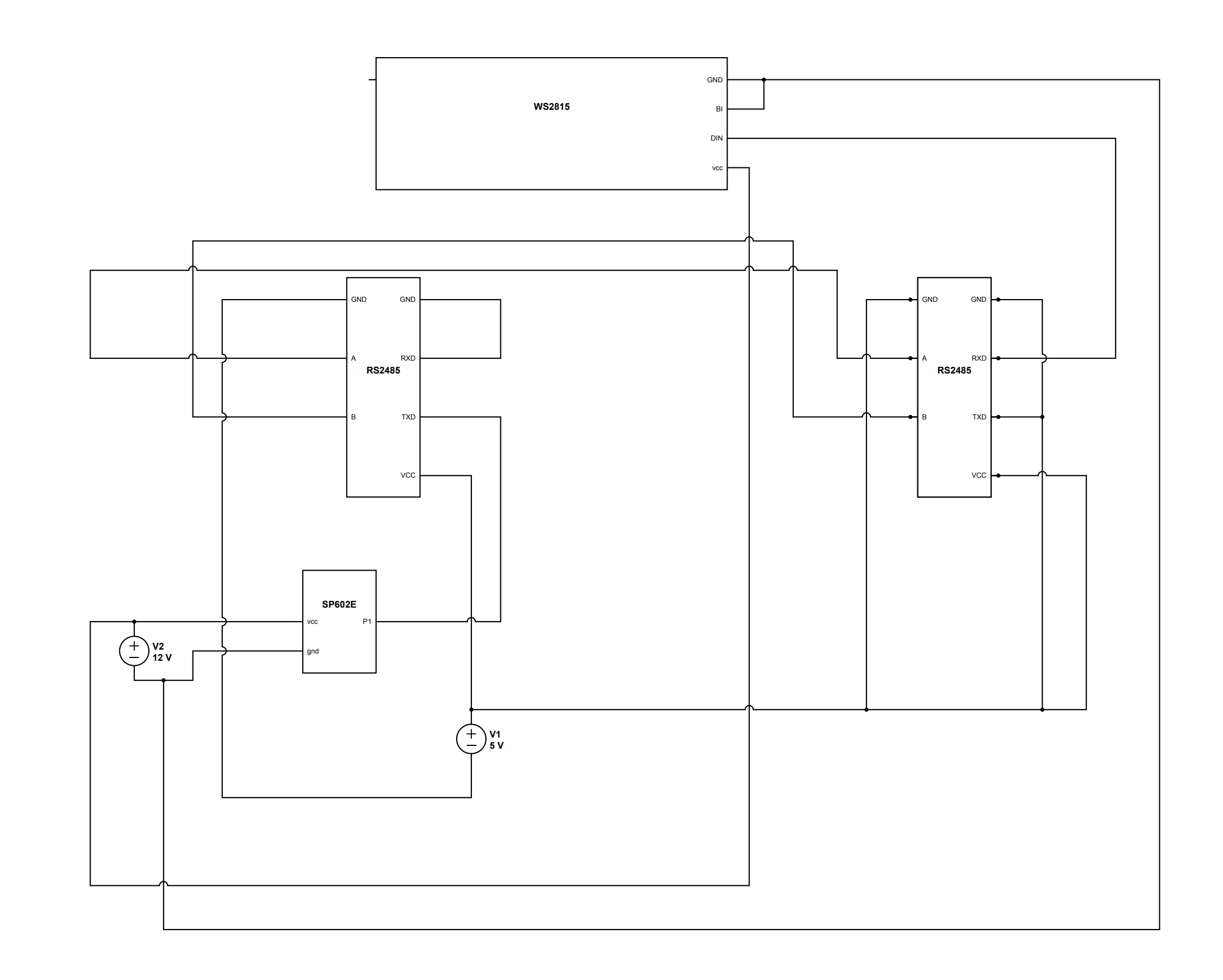
This is the current setup that is working, but I have a few questions regarding the ground RS485 setup.
The front side 485 has the one of two grounds tied to the RXD, as when it was hooked up to the actual ground it caused a doubling of voltage and increase in the LED brightness.
Based on another recommendation, the transmit (TXD) on the receiver end RS485 is grounded which once done, allowed control to the WS2815 strip.
The termination resistor was causing issues with the LEDs flickering when the power was turned off via the controller, the 120 ohm was worse then changed to a 100 ohm, which reduced the flickering.
Once removed, the LED strip had no more bleed over. I cannot find an actual spec sheet for these particular RS485s, however they do say that they have shorting for the A+/B- (120 ohms) set, particularly for long distance transmission added into the controller.
Lastly looking at the schematics and recommended circuit for the WS2815, the secondary data (BI) is recommended to be attached to ground for the first run, then additional runs to data out from primary lines.
For the grounding setup on this, this sounds abnormal - especially on the front side 485 to me, although the second ground is still grounded to the PSU for the 485 5V in.
Is this going to cause me issues in the long run? It is actually running perfectly in this configuration with the SP602E directly input to the data line in to the 485.
Using the UART to 485 module like in this video.

