0
\$\begingroup\$

I would like to try to elaborate in detail how I think one should perform in detail practically impedance match between source and load via maximal power transfer using a L-matching network and whould like to know if my approach is correct.

Suggestion: I would like to describe now how I understood it and I would happy about any feedback on if I did it correct or wrong and how to repair it.

How I would do it:

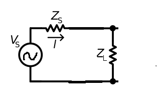
  1. We start with network consisting of source S with impedance \$Z_S\$ and load L with impedance \$Z_L\$. In general \$ Z_S \neq Z_L^*\$.

enter image description here

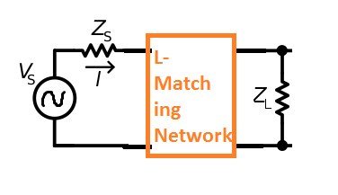
  1. What we do next. We put the L-matching network (the 'orange box') between source and load.

enter image description here

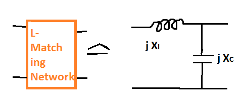
Internally a single L-matching network is a combination of a capacitor and a coil in one of the following possible configurations can be found eg here or there

Assume, we take the first one:

enter image description here

  1. The reactances \$j \cdot X_C\$ and \$j \cdot X_I\$ of the capacitor and coil are not known and if we want to archieve an perfect match, these should be adapted.

  2. Next, the most crucial part for me is which conditions should the satisfied by the still unknown \$j \cdot X_C\$ and \$j \cdot X_I\$?

My guess is that to determine \$X_C\$ and \$X_I\$ following equations should be satisfied:

(I) \$Z_S = Z_{in}^*\$
(II) \$Z_{out} = Z_L^*\$

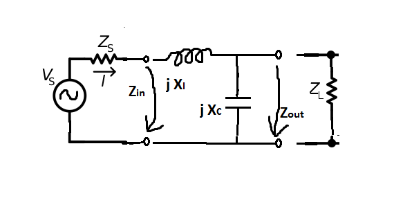
where \$Z_{in} \$ and \$Z_{out} \$ are following impedances:

enter image description here

So formally we are done at that point: \$Z_{in} \$ and \$Z_{out} \$ contain \$X_C \$ and \$X_I\$ as unknown variables and our task is to find \$X_C\$ and \$X_I\$ solving equations (I) and (II).

Questions:

A. Is in principle the procedure I have written done above to match impedance via L-matching network correctly explained?

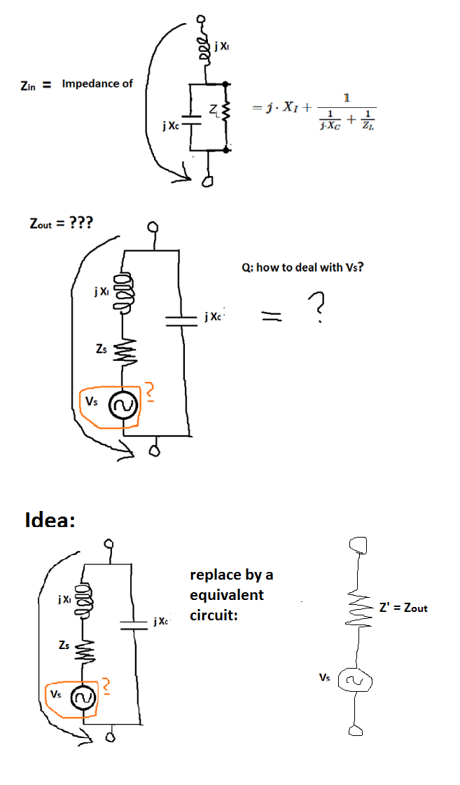
B. If the answer to A. is positive, I'm not rather sure how to to express \$Z_{out} \$ in terms of \$ Z_S, X_C, X_I\$.

\$Z_{in} \$ is rather simple: enter image description here

\$j \cdot X_{I} \$ is in series to parallel block of \$j \cdot X_{C} \$ and \$Z_{L} \$, which has impedance \$ \frac{1}{\frac{1}{j \cdot X_C}+ \frac{1}{Z_{L}}} \$, therefore

$$ Z_{in}= j \cdot X_{I}+ \frac{1}{\frac{1}{j \cdot X_C}+ \frac{1}{Z_{L}}} $$

by construction. What is \$Z_{out} \$ in terms of \$ Z_S, X_C, X_I\$?

C. Can we play verbatim the same game if we want to reach minimal signal reflection instead of maximal power transfer (for example if our load is a transmission line) with small correction that everywhere we required \$ Z_A = Z_B^*\$ we replace by the conditions \$ Z_A = Z_B \$ but esle the the steps 1-4 go throgh? Is does this procedure above only works for maximum power transfer?


Addendum - respond to Andy's concern:

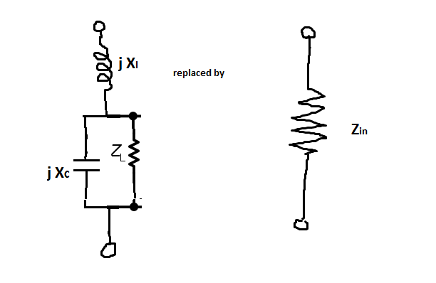
In your calculations you succeed in calculation of \$Z_{in} \$. As I said \$Z_{in} \$ by definition equals the impedance of the replacement circuit of:

enter image description here

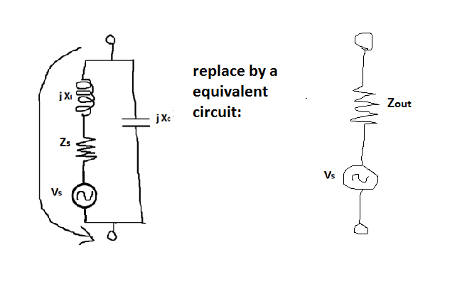
and the missing impedance is \$Z_{out} \$ which should arise as:

enter image description here

It's not clear how your calculations below can be used / adapted to calculate \$Z_{out} \$.

\$\endgroup\$
10
  • \$\begingroup\$ I would urge you to reconsider the procedure outlined in Question A...it is too complex. Start by setting aside reactive components of \$Z_S\$ and of \$Z_L\$. They become \$R_S, R_L\$. Prof. Ali M. Niknejad applies a nicely intuitive approach: rfic.eecs.berkeley.edu/142/pdf/module6.pdf \$\endgroup\$
    – glen_geek
    Commented Dec 3, 2021 at 2:15
  • \$\begingroup\$ @glen_geek: but are there any conceptual errors in my reasonings in steps 1-4? \$\endgroup\$
    – user267839
    Commented Dec 3, 2021 at 11:27
  • \$\begingroup\$ I can see that by including reactive component of \$Z_S\$ and reactive component of \$Z_L\$, you may make the goal of impedance match unachievable if they dominate the two purely reactive components of the L-network....be prepared to accept a sign-change of the components in the L-network. Or from a different point of view, there is a reactive value of \$Z_S\$ when combined with a reactive value of \$Z_L\$ that give a "matched" condition: no L-network is needed. \$\endgroup\$
    – glen_geek
    Commented Dec 3, 2021 at 17:44
  • \$\begingroup\$ @glen_geek: you mean that the pure mathematical part may fail if we allow arbitrary \$ Z_S \$ and \$ Z_L \$ as initial parameter and aim as our goal to find capacitor & coil with appropriate values \$ X_C \$ and \$ X_I \$ satisfying (I) \$Z_S = Z_{in}^*\$ (II) \$Z_{out} = Z_L^*\$ stated in 4? Then is could happen that such \$ X_C \$ and \$ X_I \$ not exist? \$\endgroup\$
    – user267839
    Commented Dec 4, 2021 at 21:06
  • \$\begingroup\$ There will always be component values of the L-network to achieve match. Be aware that their sign may switch, turning L's into C's (and C's into L's). I think you're approach is OK, but awkward. Also be aware that some solutions require component values that may be lossy, or require tight tolerance. That's especially true when ZS differs greatly from ZL. \$\endgroup\$
    – glen_geek
    Commented Dec 4, 2021 at 21:19

1 Answer 1

3
\$\begingroup\$

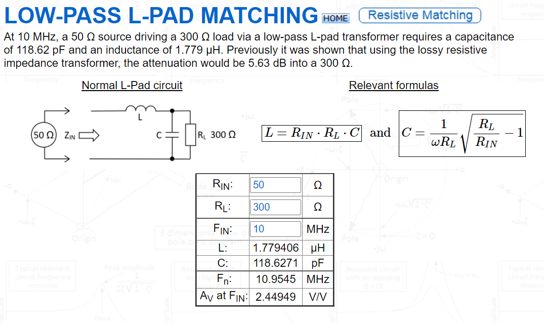
An L-pad derivation can be found on my website here. You can use the web calculator provided and here's an example of matching 50 Ω to 300 Ω at 10 MHz: -

enter image description here

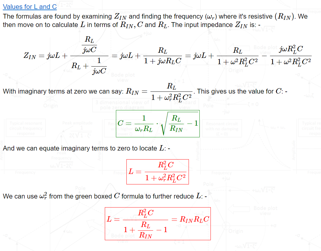
As you can see, the formulas are shown in the picture but, the derivation is shown further down: -

enter image description here

Is in principle the procedure I have written done above to match impedance via L-matching network correctly explained?

It looks about right but, given my website derives it for you, you can double check this yourself.

The Pi and T filter links also show you how to cascade to get really sharp cut-offs that can be quite appropriate for RF antenna circuits to avoid emissions that might be outside legal requirements.


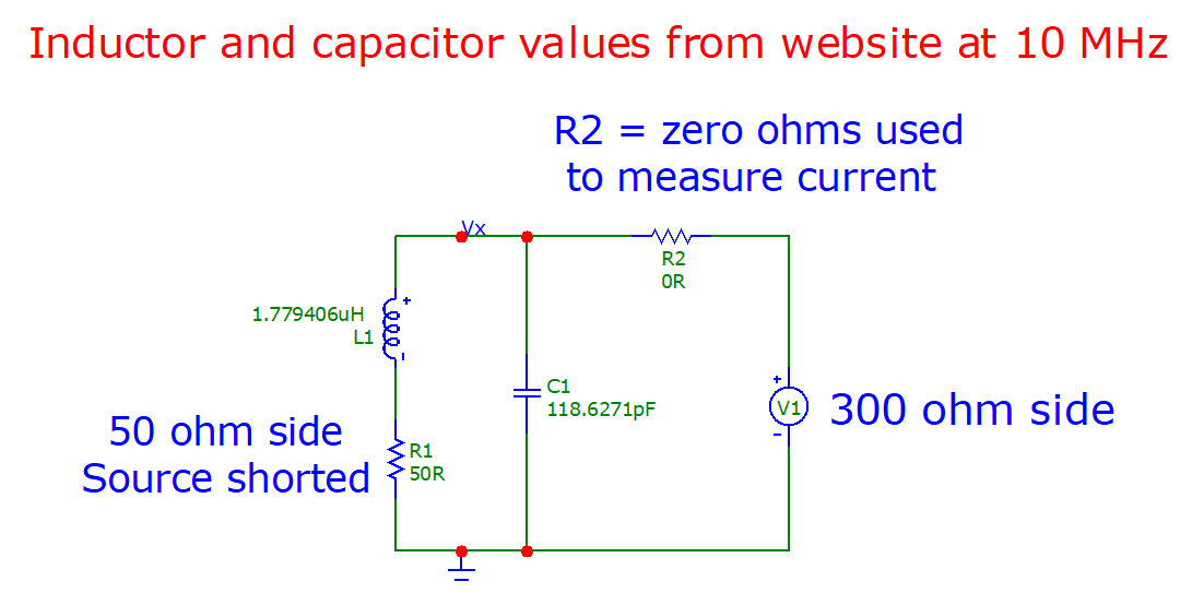
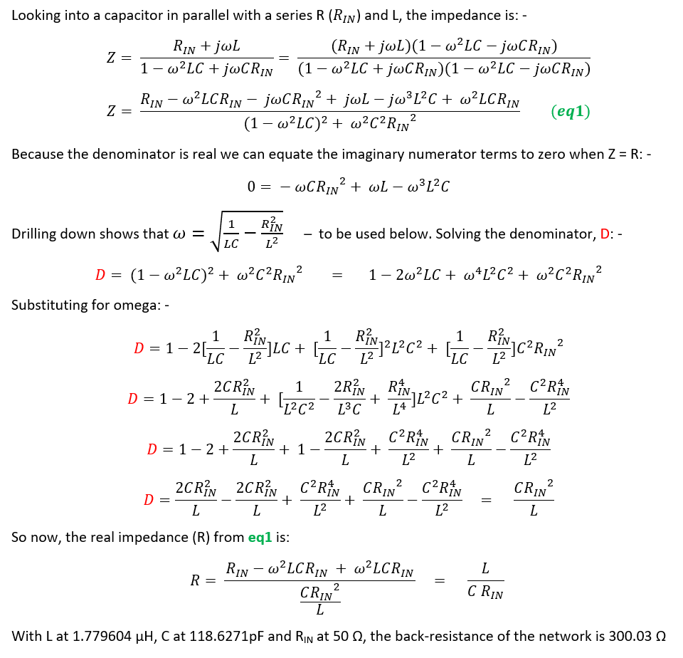
Addendum 1 - the output impedance is purely resistive and equal to 300 Ω at 10 MHz

The simulation circuit uses a source at the position of \$Z_{OUT}\$ and a zero Ω resistor to measure the phase angle of the current taken from the source: -

enter image description here

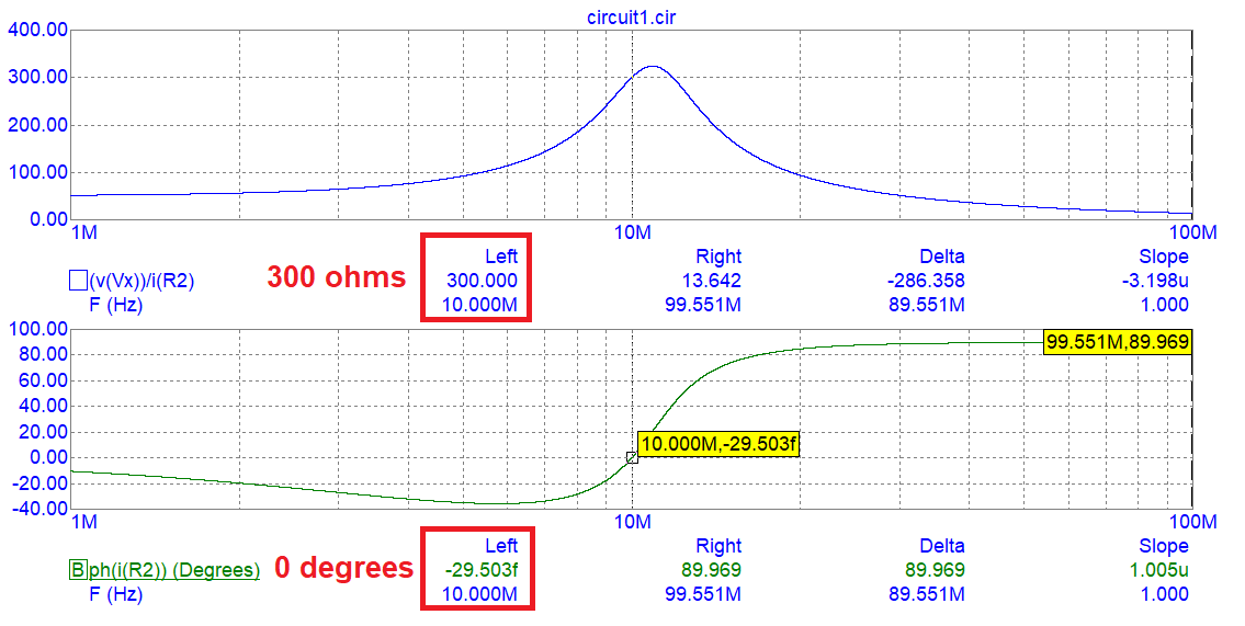
The AC analysis: -

enter image description here

I don't think that there can be any doubt about the impedance looking into the output node being 300 Ω and purely resistive. Of course if you want to prove that then just spend a couple of hours hammering your way through the maths. I'm not going to do that of course (or am I?).


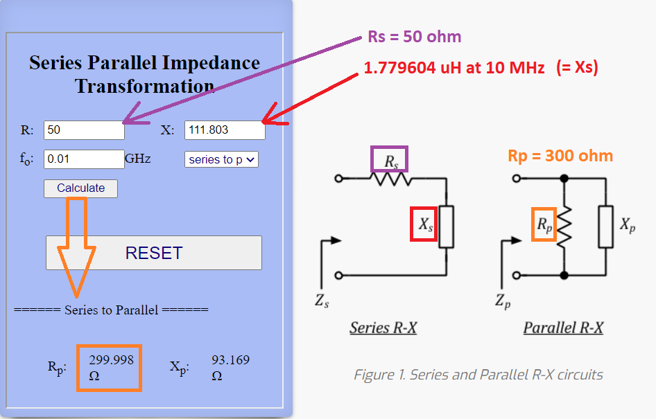
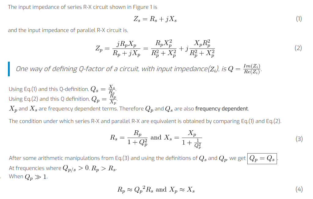
Addendum 2 - series to parallel inductor-resistor calculator: -

enter image description here

The derivation of the conversion is shown on the same website: -

enter image description here

Do you really need any more convincing? I suppose you do: -

enter image description here

\$\endgroup\$
24
  • \$\begingroup\$ Thank you @Andy, that covers the case where the impedances of source and load are real: \$ Z_S = R_S, Z_L=R_L \$ One aspect is not quite evident there. You give a formula for \$ Z_{in} \$, the value of \$ Z_{out} \$ is not involved in your considerations. seemingly because it is not neccessary to determine \$ X_C \$ and \$ X_I \$. Do you nevertheless know how it can be calculated? \$\endgroup\$
    – user267839
    Commented Dec 4, 2021 at 20:37
  • \$\begingroup\$ I think you need to run with this yourself now. I've shown you the proofs for resistive impedance. Just modify my technique for complex impedance OR, recognize that you can cancel the reactive elements with the opposite value series reactances thus leaving you you with resistive values. This is how you'd match an antenna to a complex driver impedance. \$\endgroup\$
    – Andy aka
    Commented Dec 4, 2021 at 20:43
  • \$\begingroup\$ what is a 'driver' as technical term in this context? is it used synonymously to 'source'? \$\endgroup\$
    – user267839
    Commented Dec 4, 2021 at 20:58
  • \$\begingroup\$ as well there is problem why as I think it becomes rather more difficult to calculate \$ Z_{out} \$ than \$ Z_{in} \$ and why your technique for calculations of cannot \$ Z_{in} \$ be straight forwardly adapted to calculate \$ Z_{out} \$. take a look at the picture I added below question B. to emphasize the problem I have now: \$\endgroup\$
    – user267839
    Commented Dec 4, 2021 at 22:19
  • \$\begingroup\$ the calculation of \$ Z_{in} \$ as you showed is a simple yoga with parallel and serial impedances, the techniques to do it are well known. we calculate at first the impedance of parallel \$ jX_C \$ and \$ Z_S \$ and then add to it \$ jX_I \$ according to calculation rule for impedances in series. it's easy. the calculation of \$ Z_{out} \$ includes the signal generator as well. how should it be treated in calculation of \$ Z_{out} \$? should it be completely ignored? \$\endgroup\$
    – user267839
    Commented Dec 4, 2021 at 22:19

Your Answer

By clicking “Post Your Answer”, you agree to our terms of service and acknowledge you have read our privacy policy.

Not the answer you're looking for? Browse other questions tagged or ask your own question.