A time varying magnetic field \$\vec{B}\$ induces an electric field \$\vec{E}_{induced}\$ which satisfies the equations
$$\nabla \cdot \vec{E}_{induced} = 0$$
$$\nabla \times \vec{E}_{induced} = -\frac{\partial\vec{B}}{\partial t}$$
Note: If a conductor is located within the electric field, the induced electric field will cause the electrons in the conductor to rearrange. This rearrangement will cause a reaction electric field \$\vec{E}_{reaction}\$ to be created which satisfies the equations
$$\nabla \cdot \vec{E}_{reaction} = \frac{\rho}{\epsilon_0}$$
$$\nabla \times \vec{E}_{reaction} = 0$$
The total electric field \$\vec{E}_{total}\$ is given by
$$\vec{E}_{total} = \vec{E}_{induced} + \vec{E}_{reaction}$$
The voltage drop along a curve \$\gamma\$ which begins at point \$P_1\$ and ends at \$P_2\$ is given by the integral
$$V_{\gamma}=\int_{\gamma} \vec{E}_{total} \cdot d \vec{\ell}$$
and corresponds to the work per charge associated with moving a test charge from \$P_1\$ to \$P_2\$ along \$\gamma\$. It also corresponds to
the voltage used in Ohm's law.
$$V_{\gamma} = I_{\gamma}R_{\gamma}$$
The EMF induced in a curve \$\gamma\$ which begins at point \$P_1\$ and ends at point \$P_2\$ is given by
$$\mathscr{E}_{induced}=\int_{\gamma} \vec{E}_{induced} \cdot d\vec{\ell}$$
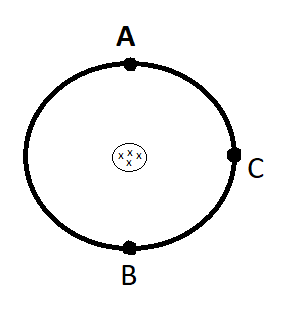
In your diagram, there are two paths between any two points. One path going clockwise around the circle, and the other path going counter-clockwise. Therefore, there is not one EMF induced between two points in your diagram, but two, one for each path.
So what is the emf between AC?
$$\mathscr{E}_{induced}=\int_{\gamma AC} \vec{E}_{induced} \cdot d\vec{\ell}$$
where \$\gamma AC\$ is either the clockwise or counter-clockwise path from A to C.
is it different from the emf between AB?
Yes, the emf "between" A and B is
$$\mathscr{E}_{induced}=\int_{\gamma AB} \vec{E}_{induced} \cdot d\vec{\ell}$$
where \$\gamma AB\$ is either the clockwise or counter-clockwise path from A to B.
In a comment, @bibo999999 asks a very good question.
So how can a voltmeter show two different results for the same measurement?
Since there are two different EMFs "between" A and B depending upon direction, what exactly would a voltmeter indicate if its leads were connected to points A and B. Obviously a voltmeter has to give one answer in any given configuration. (It turns out that a voltmeter measuring a circuit subject to a time-varying magnetic field will give different answers depending upon the location of the voltmeter. But for this answer, we will assume that the voltmeter is in one fixed location.)
If there are two paths \$\gamma_1\$ and \$\gamma_2\$ that connect two points, but in different directions, then let's call \$\gamma_2'\$ the curve made by reversing \$\gamma_2\$. Then \$\gamma_1\$ and \$\gamma_2'\$ together form a loop.
Since they form a loop, we can apply Kirchhoff's Voltage Law (KVL). The sum of the emfs in \$\gamma_1\$ and \$\gamma_2'\$ is equal to the sum of the voltage drops in \$\gamma_1\$ and \$\gamma_2'\$.
$$\mathscr{E}_{\gamma_1} + \mathscr{E}_{\gamma_2'} = V_{\gamma_1} + V_{\gamma_2'}$$
Therefore,
$$\mathscr{E}_{\gamma_1} - V_{\gamma_1} = - \mathscr{E}_{\gamma_2'} + V_{\gamma_2'}$$
Therefore,
$$\mathscr{E}_{\gamma_1} - V_{\gamma_1} = \mathscr{E}_{\gamma_2} - V_{\gamma_2}$$
What a voltmeter displays is the voltage drop through the meter itself. This can be found using Kirchhoff's Voltage Law. A voltmeter, together with its leads, and any path \$\gamma\$ connecting its leads, forms a loop. KVL says that sum of all the emfs in that loop is equal to the sum of all the voltage drops along that loop. So, what the voltmeter will display will be the emf in \$\gamma\$ plus the emf in the leads minus the voltage drop in \$\gamma\$ minus the voltage drop in the leads. That leaves the voltage drop in the voltmeter (assuming that there is no emf in the "sensitive" part of the voltmeter).
$$\mathscr{E}_{\gamma} + \mathscr{E}_{leads} = V_{\gamma} + V_{leads} + V_{meter}$$
or
$$V_{meter} = \mathscr{E}_{\gamma} - V_{\gamma} + \mathscr{E}_{leads} - V_{leads}$$
However, since we have already shown that
$$\mathscr{E}_{\gamma_1} - V_{\gamma_1} = \mathscr{E}_{\gamma_2} - V_{\gamma_2}$$
The voltmeter will read the same, whether we choose \$\gamma\$ to be \$\gamma_1\$ or \$\gamma_2\$.
QED!

