4
\$\begingroup\$

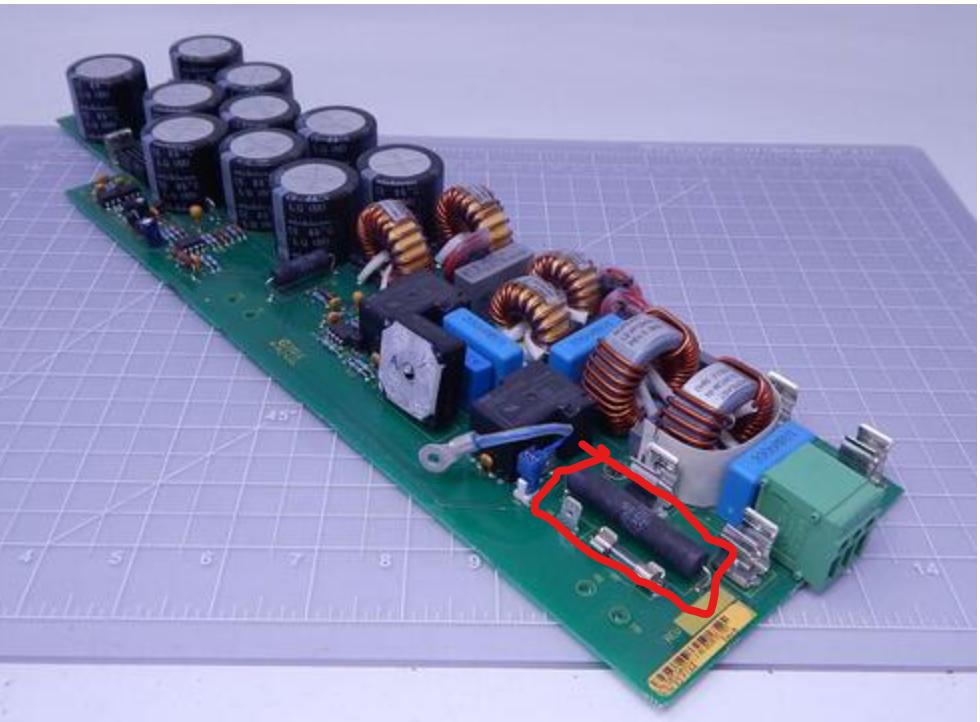
My power supply got broken. Upon further inspection, I found out that the high power resistor (15 ohm, 10 W) was broken.

Enter image description here

Unfortunately, I can't purchase such a resistor (with the same specifications, not to mention the same brand) and I don't have the schematics and am not sure what exactly the resistor is for (what devices does it limit the current for?) and I am wondering how dangerous would it be to:

  • Replace the resistor with a wire. That means basically no resistance and much more current flow in the close-by components. Even though I don't see components that could be affected by overcurrent, it's still something I'd do as a last resort.

  • Replace the resistor with a fuse. We can calculate the appropriate current (230 V at 15 ~ 16 A) and have it soldered. This is an even better option since in the worst case it will blow and I will save other components. The last thing I want to do is to blow the chip when now only one resistor is blown.

How appropriate do these options seem? Is there another way to solve the problem?

\$\endgroup\$
7
  • 7
    \$\begingroup\$ seeker - Just as a starting point if you can do any rev-eng: Judging by the location of that resistor, its rating & what might be a relay (black, almost rectangular, nearby), I wonder if that is a surge-limiting resistor which gets bypassed by relay contacts after a few seconds? Look at the PCB tracks. Is the resistor in series with one of the mains inputs? Do the relay contacts short out the resistor? If all of that is true then a possible failure mode is that the relay (or its timer that closes the contacts) has failed & the mains supply was passing thru the resistor continuously. Good luck! \$\endgroup\$
    – SamGibson
    Commented Apr 10, 2022 at 6:31
  • 1
    \$\begingroup\$ Now we're talking. @SamGibson I guess you're right... I will check PCB tracks in few hours and will get back but most likely you're right. Since: black, almost rectangular thingy is a relay and indeed relay 'clicks' after second or two after turning PS on. So I need to double check the PCB tracks but I'm very certain those are in series with mains, right after two HRC fuses \$\endgroup\$
    – seeker
    Commented Apr 10, 2022 at 6:39
  • 1
    \$\begingroup\$ seeker - OK, I'm glad my comment was useful. I deliberately wrote it as a comment, as it isn't trying to answer your question about whether the resistor can be bypassed. I just wanted to give a suggestion (guess!) of where a fault might be, to have caused the resistor to fail in the first place (e.g. due to overheating, if the relay contacts don't close to bypass the resistor a short time after power-on, when the capacitors have charged up). That way, as well as replacing the resistor, you can investigate whether there is an underlying fault, and perhaps fix that too. (Be careful with mains!) \$\endgroup\$
    – SamGibson
    Commented Apr 10, 2022 at 6:48
  • 1
    \$\begingroup\$ @seeker: I fear that SmaGibson's comment might not be explicit enough. The resistor might have been designed to handle at most 2 seconds of current, but due to another failure it remained active for much longer. It therefore had time to overheat. Simply replacing the resistor will then melt the new resistor too. You should measure the voltage over the resistor, and cut the power supply if the voltage over the new resistor does not drop within a few seconds. \$\endgroup\$
    – MSalters
    Commented Apr 11, 2022 at 9:24
  • 2
    \$\begingroup\$ That's how I understood Sam's comment @MSalters.... Anyway problem is now solved. First of all - the resistor in question was in fact surge limiting resistor. Next, the problem was in fact in broken relay (mechanical issue, resistor bypass contacts were not shorted even when coil was energized). And as much as I was tempted to simply remove resistor, I actually found two 30 ohms resistor with 10W dissipation power and soldered them in parallel. I've also checked board with thermal camea to make sure thee are no excessive heat. So while there might be other problem, I am very certain it's fixed \$\endgroup\$
    – seeker
    Commented Apr 11, 2022 at 10:44

3 Answers 3

14
\$\begingroup\$

The brand is not relevant. And you can most definitely buy a resistor that would fit, i.e., with same resistance and approximate power rating.

You're assuming that the rest of the supply still works. That may or may not be true...

it's really hard to find 15 ohm 10 W resistor in my area right now

Harder than reverse engineering the supply to understand why the 15 ohm resistor was there? Nah, I don't buy that, unless your time is free... You can in fact do both: order a resistor from China, for cheap, but with slow delivery. In the meantime, reverse-engineer the supply at least around the resistor. Then you'll figure out what the resistor is for, and that in most likelihood it was needed :)

I've already tested the rest by applying fuse for few seconds, PCB provides expected outputs, so not 100% sure but 99% everything else works. What's your opinion on suggested workarounds?

The designers used a resistor for a reason. You'd have to reverse engineer the circuit, make sure you understand their reason, and then satisfy yourself that the workarounds won't break something. Engineers don't put such elements in the circuit for no reason. Do not use a wire or a fuse.

\$\endgroup\$
3
  • \$\begingroup\$ Well now I get your point. I wanted to know likelihood I would damage anything by using e.g. fuse with correct rating. My bad since I wanted exact answer without providing schematics which is indeed not adequate . \$\endgroup\$
    – seeker
    Commented Apr 10, 2022 at 6:19
  • 3
    \$\begingroup\$ @seeker, no fuse has a correct rating. A fuse is simply a wire that's been engineered to melt under certain precise conditions. \$\endgroup\$
    – Mark
    Commented Apr 10, 2022 at 20:24
  • \$\begingroup\$ @seeker: What you will damage is at least the fuse. From P and R we can deduce V and I; about 12V and 1.2A. If you put in an 1.2A fuse, the remainder of the circuit would see a 12V higher voltage. Since the series resistance would now be lower by 15 Ohm, the current goes up and your 1.2A fuse melts. Hopefully it's the first thing to melt. \$\endgroup\$
    – MSalters
    Commented Apr 11, 2022 at 9:19
7
\$\begingroup\$

With out a schematic it is difficult to know how important the exact value of the resistor is. Using a fuse or wire short would not be adequate at all. (Even if it does initially work with one of those it would most likely fail after a short time under load, or you might damage the equipment that is being powered with the supply.) Other than a proper value replacement some options would be to use multiple resistors to create a replacement resistor. For example you could use two 30 ohm resistors wired in parallel, or two 7.5 ohm resistors wired in series to create a 15 ohm replacement. The replacement resistors would need to have a wattage that totals up to (or greater than) the original part. You could even take this idea further by using 3 or 4 resistors to recreate the correct value of resistance and wattage. With equal value resistors the required wattage for each divides equally.

\$\endgroup\$
1
  • \$\begingroup\$ Thanks for suggestion, indeed there is space on PCB so worth trying \$\endgroup\$
    – seeker
    Commented Apr 10, 2022 at 6:08
1
\$\begingroup\$

Many power supply designs may be subject to inrush currents that, depending upon the line phase when a device is plugged in, may exceed normal operating currents by an order of magnitude or more. Even if it would take 10ms or less for currents to fall back to normal, such a massive over-current event may be sufficient to cause damage even within that short time. Adding a series resistor to the input of a power supply stage will generally reduce efficiency, but also makes it easy to quantify the maximum possible inrush current. Bypassing such a resistor may result in a supply that will work, at least for awhile, but will be susceptible to damage from high inrush currents. While some resistors may be unnecessary (because a variety of factors would limit inrush currents even without the resistor) the amount of engineering effort necessary to determine that a resistor may be eliminated may exceed the amount of engineering effort that was expended on the entire power supply design.

\$\endgroup\$

Your Answer

By clicking “Post Your Answer”, you agree to our terms of service and acknowledge you have read our privacy policy.

Not the answer you're looking for? Browse other questions tagged or ask your own question.