1
\$\begingroup\$

I have a guitar amplifier (Blackstar ID Core 10 v2). Its power brick has gone bad last year, and I have been searching for a power brick ever since.

This device works with 6.5 V, 3 A DC. It is pretty uncommon as far as I can tell. The worst part is, I cannot get a replacement power brick here in Turkey. It just doesn't exist here and I cannot import one.

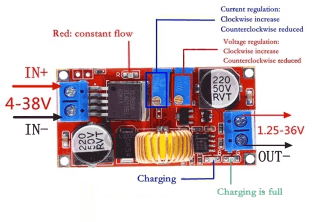
So what I am planning to do is: get a 12 V, 3 A or a 9 V, 4 A power brick, and an XL4015 DC/DC voltage (and current) regulator (I think it is a "switching" regulator, but I don't know the difference between switching and linear regulators).

I will desolder the power plug of the amp, solder the plug to the INPUT of the module, and the power cables of the amp to the OUTPUT of the module. So, the module's input will be 12 V, 3 A or 9 V, 4 A, and its output will be 6.5 V, 3 A (Don't worry, I will use a multimeter). I will put a small heatsink on the IC, but heat is still concerning me.

XL4015 Module

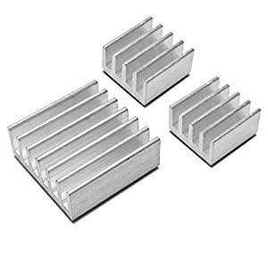
The heatsink that I'm talking about

I read online that these modules tend to get hot to touch at 3 A even though they are rated for 5 A. This is when I realized I needed a heatsink.

Upon further research, I learned that if the voltage difference between input and output is too big, it might just burn the IC right away as it would get too hot. I have seen a temperature calculation for linear regulators, which is: voltage difference x ampere = temp difference. I don't know if this applies to my situation but I wanted to make sure because a small passive heatsink can cool 2 W of heat, but 16.5 W of heat? IDK and I don't think so.

Does the calculation above apply to my situation? If not, what kind of temperature would I get? Would a small heatsink be enough? Should I be doing this project?

\$\endgroup\$
6
  • \$\begingroup\$ It's not linear but a switch-mode one. Cooling won't be easy as the top of the IC is plastic and won't conduct much heat. \$\endgroup\$
    – winny
    Commented Aug 30, 2022 at 14:29
  • \$\begingroup\$ You can cool it at the bottom side using a thermal pad like TG-A3500-15-15-3.0 between the board and a large metal plate below \$\endgroup\$
    – Jens
    Commented Aug 30, 2022 at 18:08
  • 2
    \$\begingroup\$ For a linear regulator, voltage difference x current is dissipated power, not temperature. \$\endgroup\$
    – ocrdu
    Commented Aug 30, 2022 at 19:22
  • \$\begingroup\$ @winny Thank you for commenting! It appears to be hard to cool, yes. I'm planning on buying XL4016 which the IC's are directly connected to heatsinks. \$\endgroup\$
    – Emirko
    Commented Aug 30, 2022 at 20:33
  • \$\begingroup\$ @Jens Thanks for the cool idea! It looks like a really good plan, but I plan on buying XL4016 now, which has it's own cooler. \$\endgroup\$
    – Emirko
    Commented Aug 30, 2022 at 20:34

1 Answer 1

2
\$\begingroup\$

A guitar amplifier is not a continuous load, you may be fine as-is.

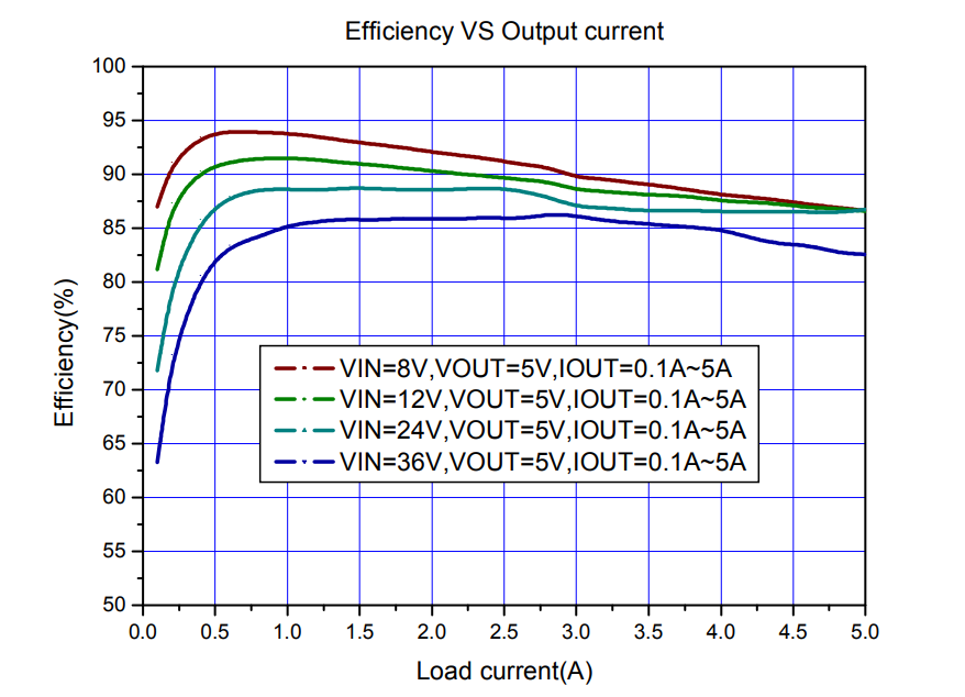
The XLSEMI XL4015 typical system efficiency is given as about 85-90% (5V out) with higher efficiencies for lower input voltages. enter image description here

The dissipation is not the simple (Vin-Vout)* Iout + Vin*Iq that you'd expect from a linear regulator- that does not apply here.

Which implies you should use the 9V option (also if the regulator fails, the circuit has a better chance of surviving). If we assume 88% efficiency, that's 2.65W loss, which is quite a bit. If it was all in the chip that would result in about an 80°C rise in die temperature, so about 120°C die temperature if the area around the PCB is 40°C. That's pretty close to the maximum 125°C Tj, but some of the losses will be in the Schottky diode and some in the inductor etc.

You could get a small stick-on heatsink as you've shown (they're used on Raspberry Pi units, and very cheap to buy online) and/or (if the back of the PCB is flat) use a silicone thermal transfer pad (can be bought online or salvaged from an old flat-screen TV etc.).

But maybe you should try playing at maximum volume and see how it behaves before taking such measures. The low 6.5V output voltage suggests it does not really deliver that much power to the load. If it's a class D bridging type working into a 4\$\Omega\$ load, less than 1.5W so the unit may run quite cool without doing much.

P.S. XLSEMI also makes an XL4016 which has a much lower Rds(on) MOSFET- 0.06 ohm vs. 0.04 ohm typical, so power dissipation should be quite a bit less.

\$\endgroup\$
1
  • 2
    \$\begingroup\$ Thank you so much for putting effort into this! It seems like XL4015 module might need some work for cooling, whereas XL4016 module has it's own cooling which looks something much better than I could ever do. Since I never go above %30 volume because it is too loud for a dorm room/family home, my chances looks better. Also, as you recommended, I will get the 9V power brick. Again, thank you so much sir. I was feeling desperate, and it feels good to know that there's still a chance for this amp. \$\endgroup\$
    – Emirko
    Commented Aug 30, 2022 at 20:26

Your Answer

By clicking “Post Your Answer”, you agree to our terms of service and acknowledge you have read our privacy policy.

Not the answer you're looking for? Browse other questions tagged or ask your own question.