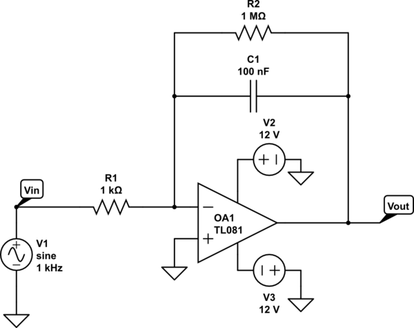
This is an integrator:
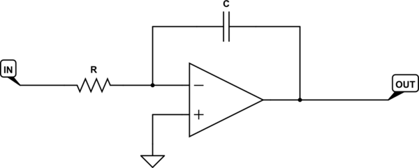
simulate this circuit – Schematic created using CircuitLab
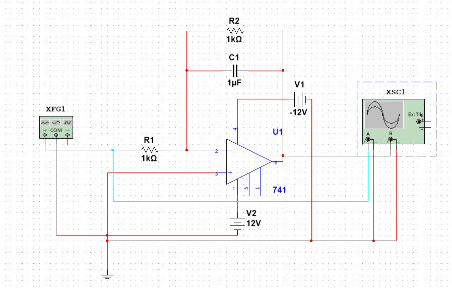
What you have built is not an integrator. The presence of R2 in your circuit turns it from an integrator into a voltage amplifier with gain −1, which attenuates frequencies above a few hundred Hertz and introduces all the phase shifts associated with such a low-pass filter.
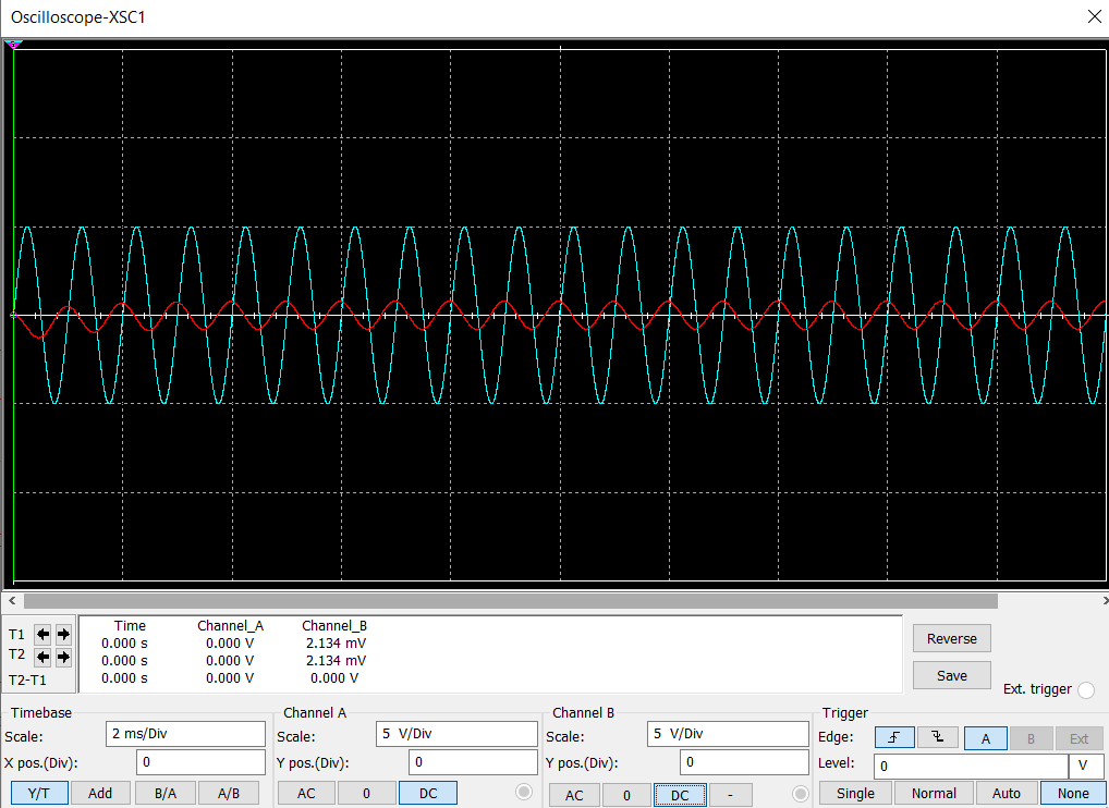
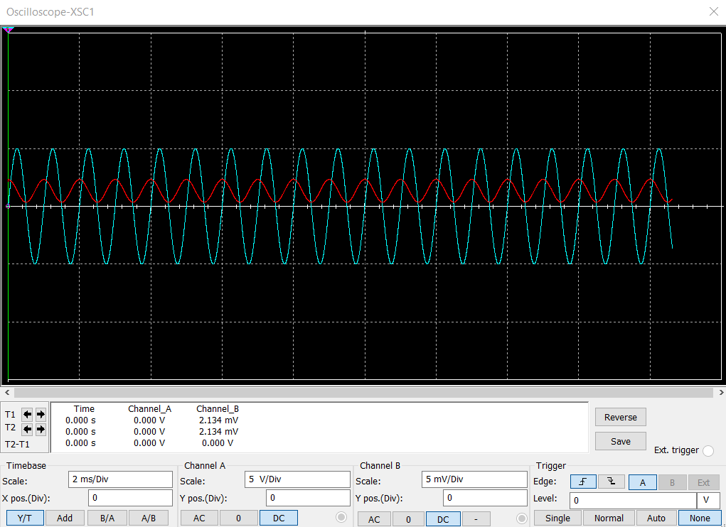
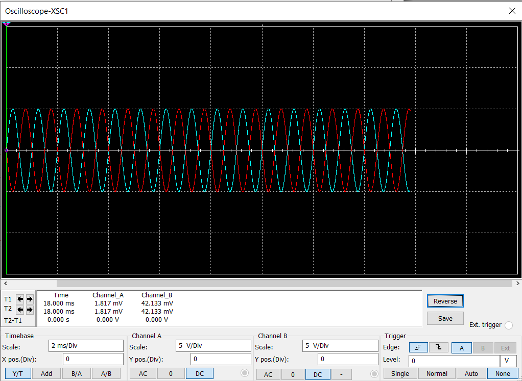
For this low-pass filter, there is a range of frequencies of input for which the phase shift will be 90°. Outside of that range you can expect phase shift to be different from 90°. Your 1kHz input apparently lies slightly outside that range, and consequently, you see the not-quite-90° phase shift in your output.
By changing C1 to 1nF, what you have done is set the cut-off frequency of this low-pass filter near 1MHz. At the comparatively low frequency of 1kHz (the frequency of your test signal), the impedance of C1 is so high compared to R2, that R2 dominates, and C2 might as well not even be there. To such an input signal, the circuit appears to be:
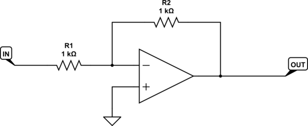
simulate this circuit
That's a classic inverting amplifier, with gain of \$-\frac{1000}{1000}=-1\$, and that's why you see the output is just an inverted version of the input.
When you integrate \$sin(t)\$, you don't get \$cos(t)\$, you get \$cos(t)\ + c\$, where \$c\$ is the constant of integration. That constant is directly related to the initial charge on capacitor C1 at time \$t=0\$. This means you will initially see an offset in the output sinusoid, but R2 will tend to bleed away average charge on the capacitor that contributes to that offset, and the result is that eventually the output sinusoid becomes centered around 0V. Interestingly, if the input were a cosine function like \$cos(t)\$, this constant is 0, because the anti-derivative of \$cos(t)\$ is \$-sin(t)\$, and \$-sin(0)=0\$.
Your circuit won't behave as you expect an integrator to behave, because it's not an integrator. It's a low pass filter, with gain approaching −1 at low frequencies, and approaching 0 at high frequencies. However, the larger R2 is, the closer to an integrator you get. When R2 is infinity, then you have an integrator.
In most integrator applications, the biggest problem to overcome is the non-idealness of the components involved. The op-amp doesn't have infinite input resistance. It doesn't have zero output resistance. It has limited bandwidth and slew rate, and worst of all, it has input offset voltage.
This latter imperfection causes integrators to accumulate an error in the output over time, meaning that even with zero input, the output rises or falls, slowly and linearly, until the op-amp saturates. The most common fix is to install a very large resistance across the feedback integration capacitor, to "bleed" away any accumulated erroneous charge. That's why you see R2 present in most integrator implementations. However, 1kΩ is way too small. The resistance we use is usually of the order of megohms.
Technically, for the circuit to still be an integrator, the resistance R2 must be much larger than the impedance of C1 at all frequencies for which the system is expected to operate. Otherwise its "bleeding" action becomes significant, and detrimental. In other words, C1 must be the dominant (low) impedance in that parallel pair for all frequencies of interest.

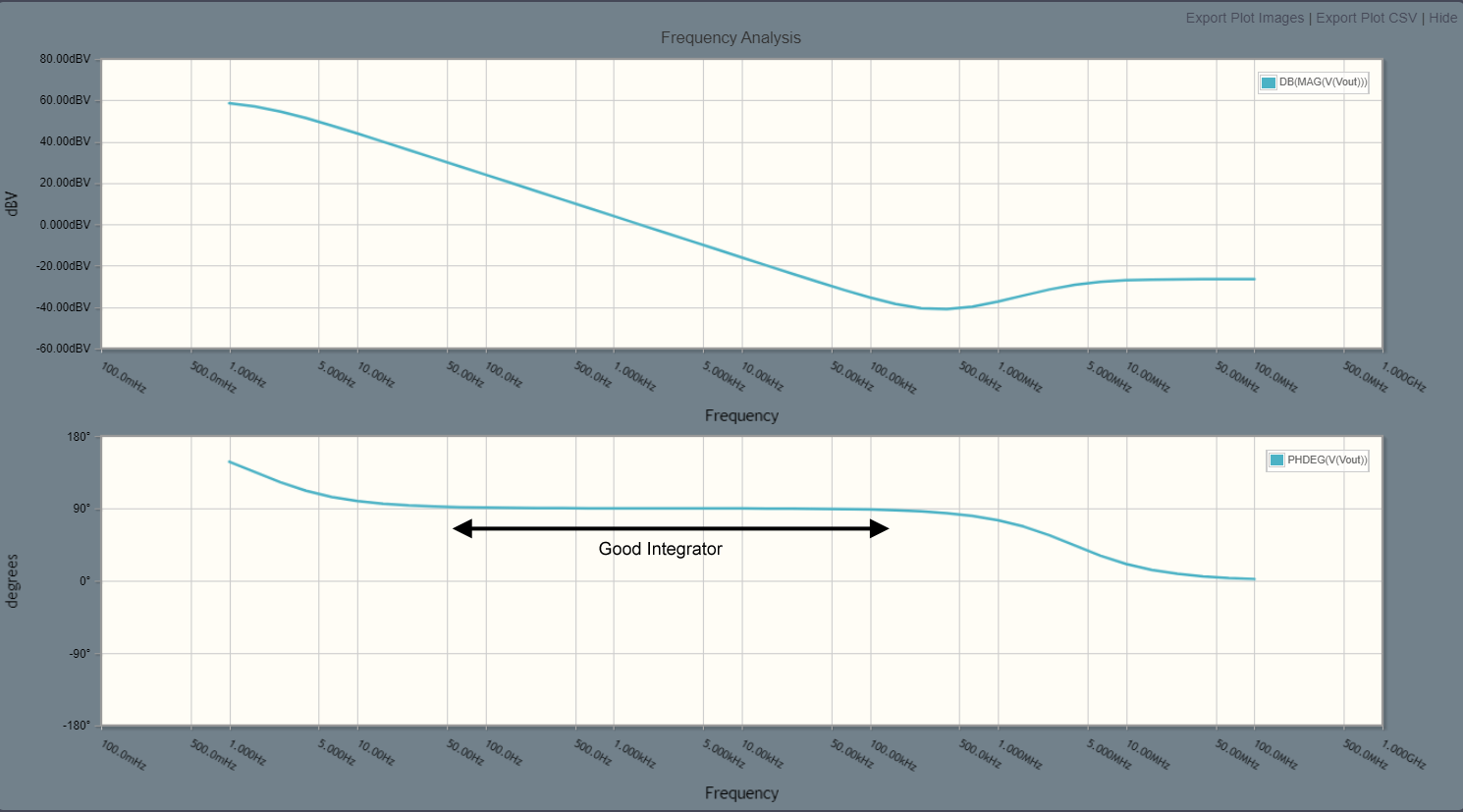


.ACanalysis and you'll see exactly what magnitude and phase different frequencies will have. \$\endgroup\$