0
\$\begingroup\$

I have a problem issue of understanding. I have to characterize a circuit with some specifications that i have to respect :

"Implement an N-channel JFET circuit allowing a source with an internal impedance of 100 Ohms, a frequency range 200 Hz-5kHz and an amplitude of 2V peak to perform a voltage attack with a unit gain on a load of 100 Ohms with the minimum distortion. The power supply will be +/-12V"

How can i find the value of my bridges resistors (R1 and R2) and the value of my emittor resistor Re ? I don't know which way i have to take to resolve this problem ;( We know that the gain is = 1 so maybe we have to use it to find Vs ? or Ze and Zs ? and then use that to find R1 and R2 ??

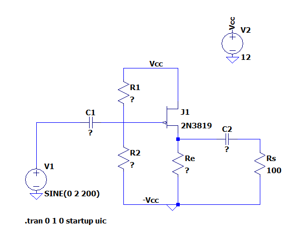
LTSPICE schematic common drain

\$\endgroup\$
5
  • 1
    \$\begingroup\$ Well, you could start by using the correct symbol for the 2N3819. 2nd you should state what reading you have done and where your specific problem lies in the understanding. Maybe you could also explain this: perform a voltage attack \$\endgroup\$
    – Andy aka
    Commented Dec 22, 2022 at 16:08
  • 1
    \$\begingroup\$ Also, you're going to need to apply bias to the gate. \$\endgroup\$ Commented Dec 22, 2022 at 16:58
  • \$\begingroup\$ Spehro Pefhany You mean sizing the resistors to bias ? or ? \$\endgroup\$
    – ktnl527
    Commented Dec 22, 2022 at 17:11
  • \$\begingroup\$ @ktnl527 A couple of points on the schematic... Usually we would call a resistor Re if it was in the emitter circuit of a bipolar transistor, for an FET we would call that one Rs because it is in the FET's source circuit. The one labeled Rs would probably be called Rl for 'load'. R1 and R2 are not connected to the gate, you can tell this because there is no dot at the junction, if you tried to simulate this it would not work correctly. The node labeled -Vcc is ground, so you don't need to label it -Vcc. That's usually seen when there is a bipolar supply. \$\endgroup\$
    – GodJihyo
    Commented Dec 22, 2022 at 17:55
  • \$\begingroup\$ GodJihyo Thank you for your comment GodJihyo :O !! (I prefer Sana btw haha) \$\endgroup\$
    – ktnl527
    Commented Dec 22, 2022 at 18:32

1 Answer 1

2
\$\begingroup\$

The component values of this circuit are extremely non-critical. R1 and R2 especially can be off by an order of magnitude from their ideal values without affecting the circuit much.

Let's start with Re, since this part is the only one that has to be somewhat accurate. To make it simple, let's operate the JFET at its minimum guaranteed Idss (zero gate-voltage drain current). The datasheet specifies it as 2mA. This means that any 2N3819 will always be able to pass at least 2mA with a gate-to-source voltage of 0V or less. This gives us the lowest possible output impedance within the datasheet's guaranteed characteristics for this JFET.

Let's also assume that you want to bias the output voltage (J1 source pin) at 4V. This is a rather arbitrary choice, but it leaves some headroom in case the JFET is better than specified and needs some negative gate-source voltage to turn it off enough so that it only passes about 2mA. (If the JFET is better than the datasheet minimums, the output quiescent voltage will go up, and we don't want it to bump into the supply voltage.)

As a result, we want Re to drop 4V when 2mA pass through it. This means Re = 200 Ohms.

Next, you'll have to choose R1 and R2. Since we chose to operate the JFET at Idss, its gate voltage equals the source voltage (at least if we get a 2N3819 that actually has Idss=2mA; it can and will vary). This means that the gate voltage must be 4V, so R1 and R2 have to form a voltage divider that divides the 12V supply down to 4V. Only the ratio of R1 and R2 is critical, not their exact values. Since the gate leakage of the 2N3819 is so low (2nA), you could use R2 = 1 MOhm and then calculate R1 accordingly to get the voltage divider ratio correct.

Last but not least, you'll have to calculate C1 and C2. C1 forms a high-pass together with the Thevenin equivalent resistance of R1 and R2, so it'll have to be big enough to pass the lowest desired signal frequency without much attenuation. C2 forms a high-pass with Rs, the same applies there.

Also, your schematic drawing has some errors (R1/R2 are not actually connected to the JFET gate, and the JFET symbol is wrong, as Andy aka mentioned)

\$\endgroup\$
4
  • \$\begingroup\$ First of all, i want to thanks both of you especially you Jonathan S. !! Your explanations were very concise and clear for me to understand. Now I understand better the points that I were not sure about. I just wanted to know how Re was calculated ? We are not supposed to have 2kOhms ? i think i just missed that point ;3 \$\endgroup\$
    – ktnl527
    Commented Dec 22, 2022 at 17:07
  • \$\begingroup\$ Oh another question that I have : i can choose any transistors that i want among jfet n type, but i just have to adapt the other components of circuit with the caracteristics of my transistor on his datasheet right ? (Thanks!!) \$\endgroup\$
    – ktnl527
    Commented Dec 22, 2022 at 17:14
  • \$\begingroup\$ Ohhhhh and also last question, the 4V for the output voltage that you picked "arbitrary" is just to have a gain equal to 1 right ? Because Ve (source voltage) is equal to 2V peak so 4V peak to peak \$\endgroup\$
    – ktnl527
    Commented Dec 22, 2022 at 21:17
  • \$\begingroup\$ The amplifier isn't going to be very linear for a wide voltage range, it's a small-signal amplifier. A 2Vp signal is too much for it. I chose 4V for the output quiescent point to allow for variations in the JFET characteristics. If the JFET is better than the specified minimums in the datasheet, the output voltage will be higher, and we don't want it to bump into the 12V supply rail. With Re=2k, the output impedance of the amplifier will be too high to drive a 100 Ohm load, so you have to use the smallest possible Re (which is 200 Ohms with the 2N3819). \$\endgroup\$ Commented Dec 23, 2022 at 16:58

Your Answer

By clicking “Post Your Answer”, you agree to our terms of service and acknowledge you have read our privacy policy.

Not the answer you're looking for? Browse other questions tagged or ask your own question.