2
\$\begingroup\$

I apologize if this question has already been asked (which I assume it has but could not find).

I recently found out about voltage regulators after finding out that voltage dividers are not the way to go in terms of lowering the voltage for powering certain devices. I'm trying to create a small test circuit that includes an ATtiny84 and a DFPlayer Mini (both of which take 5 V to power up).

However, I also want to use a 6 VDC motor which creates a problem since I can't go over 5 V for both of the previously said devices. I thought it would be ideal to use a voltage regulator to power the other devices while still having 6 V for the motor.

I've searched online for small 78xx voltage regulators that take in 6 V, 2 A and output 5 V, 2 A but I couldn't find any.

Does anyone know where I might find them? Also sorry for any misuse of words, I'm fairly new to working with electronics.

\$\endgroup\$
9
  • \$\begingroup\$ A DC to DC converter? \$\endgroup\$
    – Solar Mike
    Commented Dec 31, 2022 at 22:41
  • \$\begingroup\$ What is the input voltage? \$\endgroup\$ Commented Dec 31, 2022 at 22:51
  • \$\begingroup\$ @StainlessSteelRat The input voltage is 6v 2A \$\endgroup\$
    – A Friend
    Commented Dec 31, 2022 at 22:54
  • \$\begingroup\$ Are you sure that you need 2A at 5V? An attiny and a DFPlayer Mini will need much less than 2A. \$\endgroup\$ Commented Jan 1, 2023 at 0:04
  • 1
    \$\begingroup\$ 78xx regulators are not low-dropout regulators. You need a low-dropout regulator. \$\endgroup\$
    – Hearth
    Commented Jan 1, 2023 at 20:48

3 Answers 3

2
\$\begingroup\$

The problem with a voltage regulator is the dropout voltage.

In order to power an ordinary regulator requires at least a minimum drop across it, perhaps 2 VDC.

If your input, 6 VDC, is only 1 VDC from the output, use a linear low dropout regulator, or perhaps a buck-boost converter.

However, if the input is well regulated 6 V, putting two silicon diodes in series would drop voltage to ~4.6 V, or one ordinary Si diode and one Schottky diode should give close to 5 V out. Use two capacitors across the output, perhaps in the range of 300 to 1,000 µFd electrolytic and 0.1 µFd ceramic, to filter the output for your intended use.

\$\endgroup\$
1
  • \$\begingroup\$ Hi! I stated that I was going to lean toward the buck-boost converter (accidentally deleted my previous comment); however, as I was doing that I ultimately fell through a rabbit hole of various sources (as well as with the low dropout regulator). I'm still trying to understand this stuff but the videos and articles I go through have me confused. By any chance do you know of any videos that talk about this particular topic? Thanks in advance! : ) \$\endgroup\$
    – A Friend
    Commented Jan 6, 2023 at 9:00
1
\$\begingroup\$

The 78xx series voltage regulators are ancient designs, and require a relatively large difference between the input and putput voltages. There are plenty of more modern "low drop out" (LDO) regulators that will run on a lower voltage.

Electric motors take a large current when starting up - perhaps 10 times the normal running current. So your 6V supply may drop noticeably when the motor is starting up, unless it is sufficiently over-specified for current. Bear that in mind while designing the system. Most motors aren't very fussy about the voltage anyway, so that may simplify your design.

You may be better off with a higher voltage supply, stepped down to 5V for the electronics, and also stepped down for the motor.

\$\endgroup\$
0
0
\$\begingroup\$

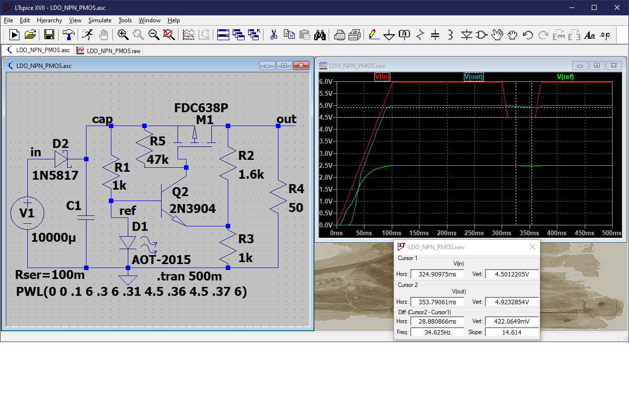
You can purchase many different LDO regulators that will do the job for you, but you might consider building your own from simple components. Here is a circuit that holds a 5V output during a 50 ms input voltage sag from 6V to 4.5V, with a 100 mA 50 ohm load. This simulates a voltage drop when the 6V DC motor starts. It uses an LED as a 2.5V reference, which may be stable enough for your purposes, or you could replace it with a more accurate reference, but the LED also provides a handy power-on indicator. The output voltage can be adjusted with the voltage divider R2 and R3. This design can work to an input/output differential (droput voltage) as low as 300 mV at 100 mA.

5V LDO using PMOS and NPN with LED reference

\$\endgroup\$

Your Answer

By clicking “Post Your Answer”, you agree to our terms of service and acknowledge you have read our privacy policy.

Not the answer you're looking for? Browse other questions tagged or ask your own question.