There are some posts and discussions how a circuit popularly called a “capacitance multiplier” could reduce low frequency ripple noise (at 50/60 Hz or 100/120 Hz) and could perform better than common (jelly bean) series regulators for higher-frequency noise ripple, as 10 kHz to 100 kHz, for instance.
I presented some context and references first, then posted questions interleaved with comments to share my points of interest - in case you see shortfalls in the examples or logic, please help to clarify the matter.
Clarification: I don’t know who named the circuit a ‘capacitance multiplier’ and I agree with Tobalt that such a circuit behaves as a ‘buffered low pass’ that could be nicknamed better (as ‘ripple smoother’, etc.), but that capacitance multiplier is preserved here for its popularity, as other misnomers in electronics - ‘Joule thief’, for instance.
Classic Capacitor Multiplier and Variants:
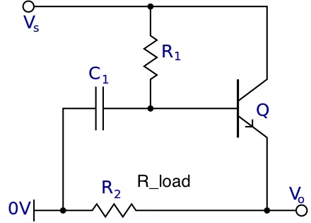
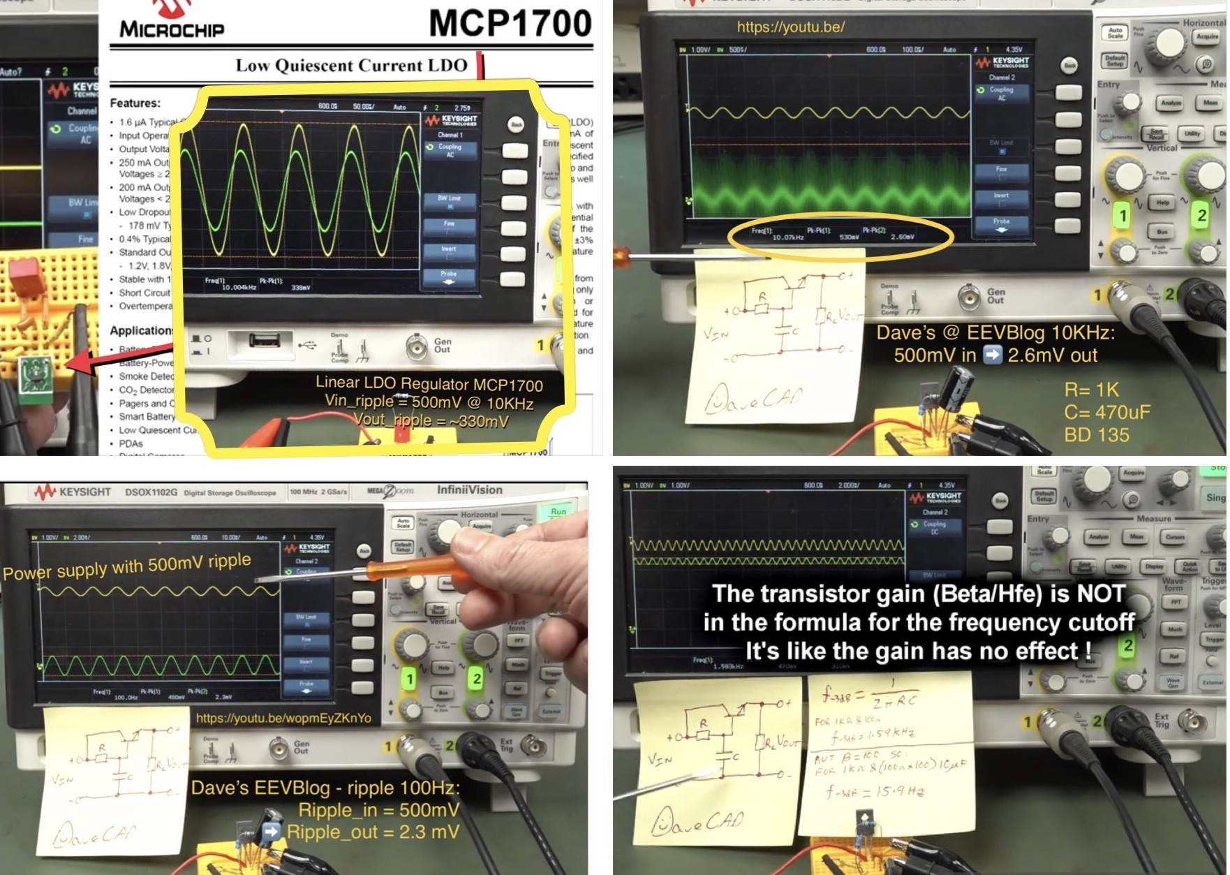
- Single-resistor + capacitor on transistor-based capacitance multiplier as seen here and explained by Dave’s EEVBlog here and his video here:
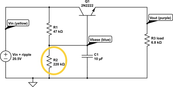
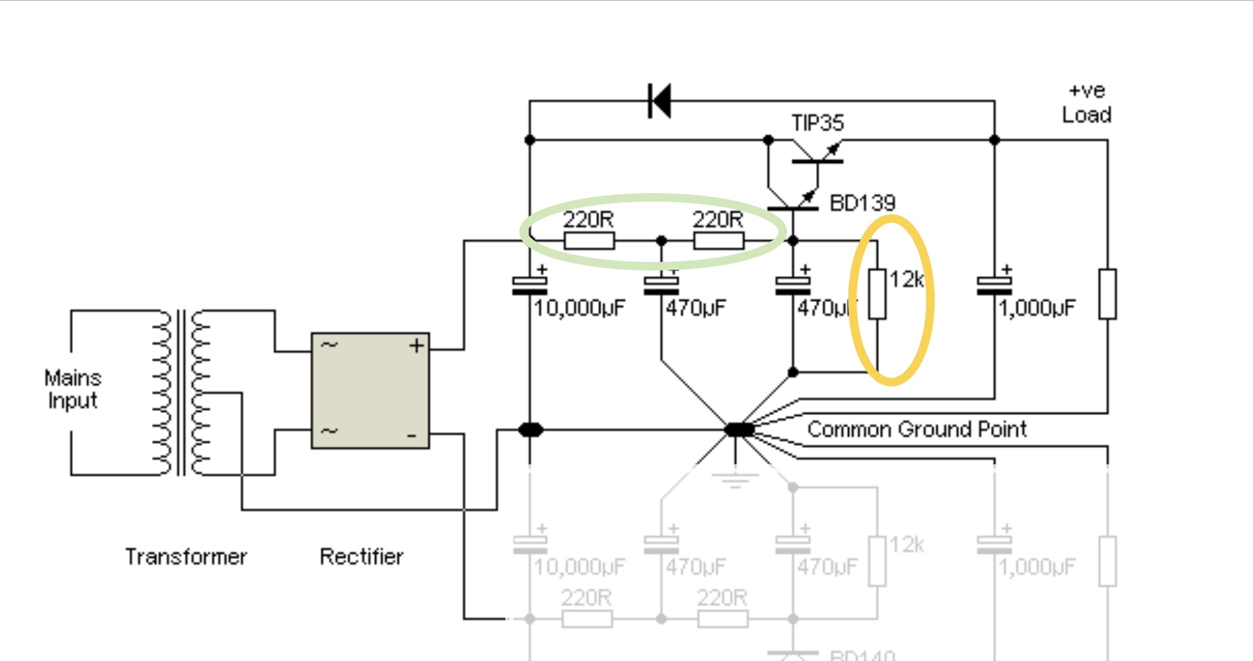
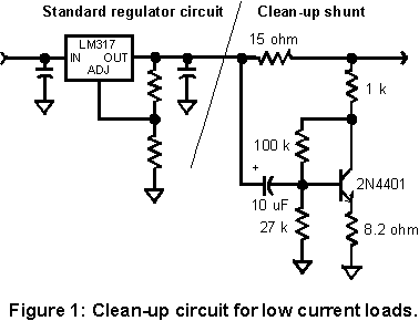
- Reduced voltage with resistor-divider + capacitor feeding transistor on capacitance multiplier to increase linear operation of the transistor - discussed here and in Elliott Sound Products (ESP here) - both highlighted in yellow:
Update: The functional improvements of using this resistor are didactically explained by ‘FesZ Electronics’ video here with simulations in LTspice.
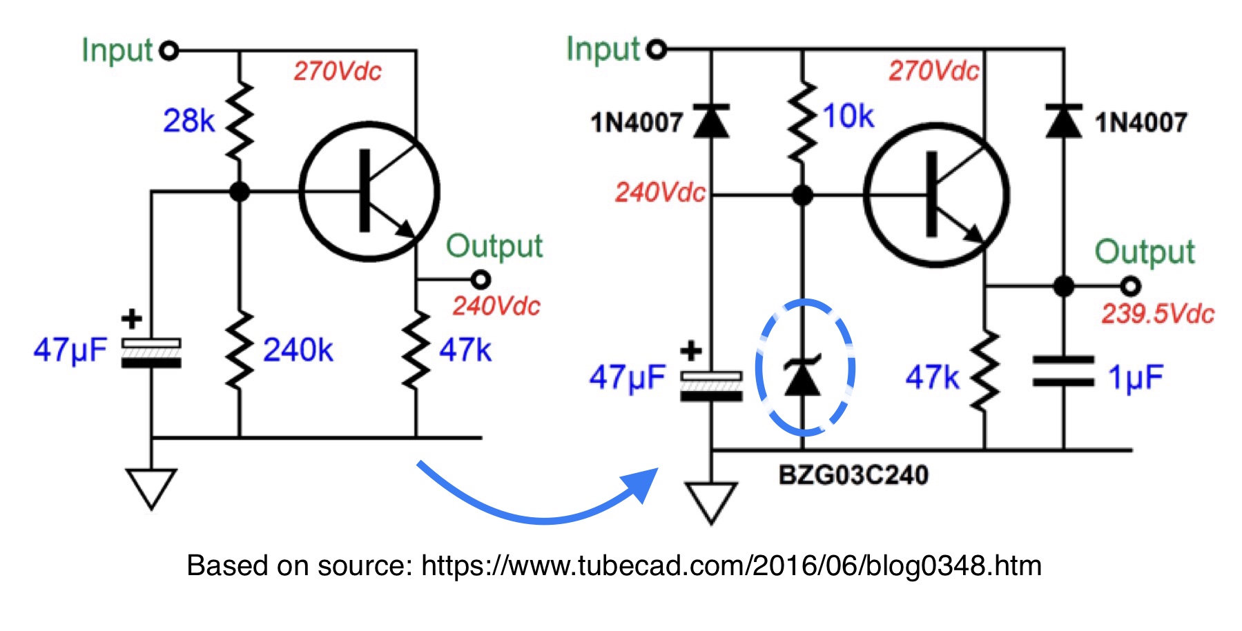
- Reduced voltage with Zener + capacitor feeding transistor - it could be seen either as a capacitance multiplier or as a crude series regulator - as seen here:
The right-side circuit includes some additional diodes for protection of the transistor, sure, as addressed and modeled by Antonio51 here (and in another post, but I could not find the link in this question).
Questions:
- Why does the capacitance multiplier have a better response ‘filtering’ the higher frequencies from Vin to Vout than a series regulator (at least for LDO as MCP1700 - upper left)?
See, for example, the screenshots from the above mentioned EEVBlog’s video - showing ripple response at 100 Hz and 10 kHz:
Clarification: the author of that ‘video tutorial’ is also the administrator of EEVBlog and he is the one who compares some ripple features of a low power LDO regulator (as MCP1700) with this capacitance multiplier.
I’m just delivering/sharing the message, from a reputable (for me) source of information.
- Regarding noise and ripple suppression, is a capacitance multiplier circuit as good as (or better than) common (aka jelly bean) series voltage regulators?
Please consider not only 100/120 Hz (linear PS) scenario, but also 10 kHz and 100 kHz (SMPS) as “ripple noise” fundamental frequency.
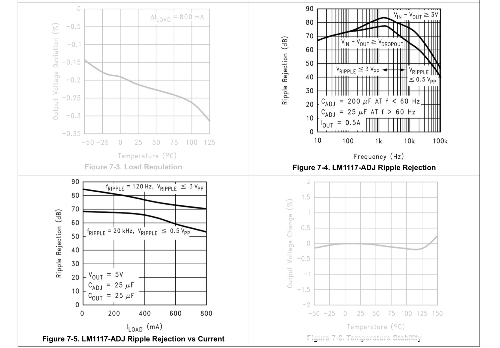
Some datasheets of common LDO regulators as AMS1117 do not post ripple rejection per frequency, but TI’s LDO LM1117 shows these curves:
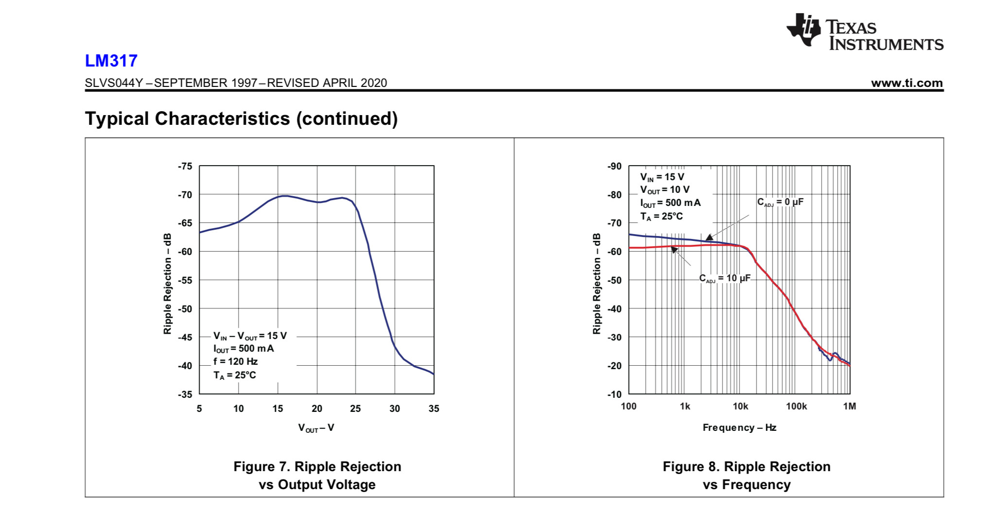
Moreover, regular series voltage regulators as TI’s LM317 show similar response as ripple rejection of about -60dB (@ 10 kHz) reducing to -40dB (@ 100 kHz), when 5 V is available as voltage differential (Vin-Vout):
On the other hand regarding the capacitance multiplier, the screenshots of that video show an attenuation that is not strongly dependent on the noise frequency - compare the responses at 100 Hz (lower left) and 10 kHz (upper right.)
- Could the above behavior be seen as “less frequency-dependent” response of the capacitance multiplier and be extended to 100 kHz or more? If not, which would be the limitations expected?
Wouldn’t it be useful as a kind of ‘power-filter’ (or amplified RC - see screenshot at lower right) to reduce the noise generated by SMPS and ‘ringing glitches’ that some diodes and inductors/transformers could cause?
Update: Regarding high frequency (HF) noise sources and their filtration, caused by SMPS, this FesZ’s video shows both in simulation and in real life how to reduce such noise, but my point here is to understand if the capacitance multiplier would be capable of reducing the HF ripple noise and be less frequency-dependent as illustrated by EEVBlog’s video.
Disclaimer: I know the terminology I used is far from the most adequate one, so I would appreciate hearing any better definitions as answers or comments to explain such phenomena.
- Could the capacitance multiplier (all 3 variants shown above) be seen as an open-loop circuit of current-amplified ripple suppression?
If this is unacceptable by any means, could someone elaborate where (and how) this ‘loop’ is ‘closed’?
I see it this way: while not being a voltage regulator, it could be loosely seen as a faster “ripple suppressor”, using the intrinsic RC response polarizing the base of the transistor, while amplifying the output current, due to hFE of the BJT.
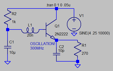
Probably a more comprehensive model of a BJT operating at really high frequencies >> 100 kHz and its internal capacitances and inductances could change the response of the component itself (BJT.) I don’t know how this would be modeled and how much this influence would be.
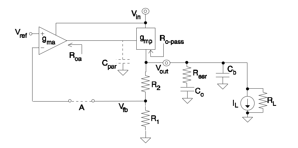
Furthermore, wouldn’t this be worse on a linear regulator with error amplifier, etc., which would be really be operated in a closed-loop layout?

