2
\$\begingroup\$

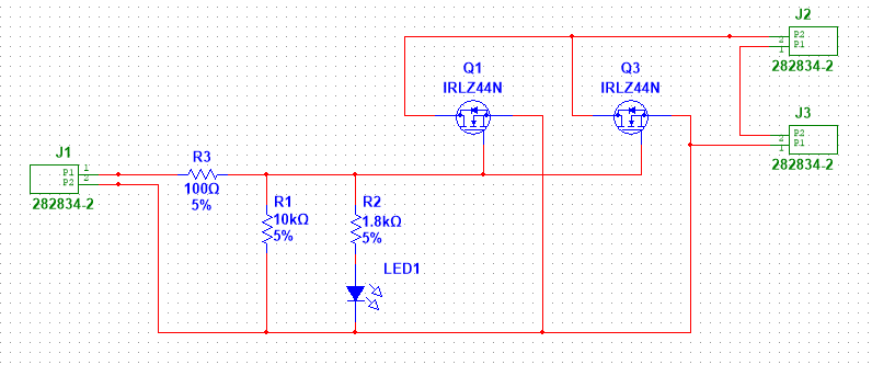
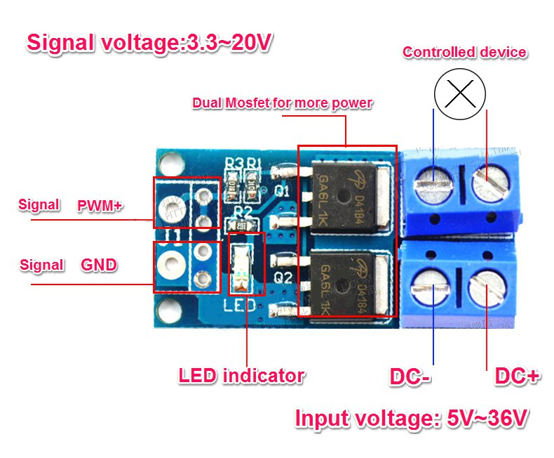
I have two of these common nMOSFET trigger modules:

d4184

The schematic is essentially this (D4184 FETs replaced with similar logic-level FET as Multisim doesn't have the D4184/AOD4184):

schematic

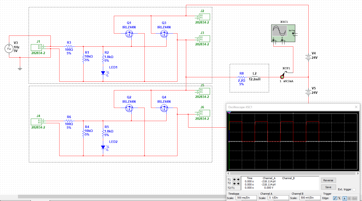
With these two modules, I'm trying to make a simple pulse motor with a half H-bridge using two power supplies (on hand). Here is the start of the iteration with two of these modules and a clock source from, say, a microcontroller:

version 1

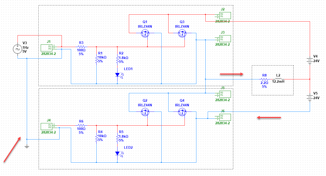
There are no freewheeling diodes yet. In the next iteration, I realize that the GND of both modules are tied together through the microcontroller like so, so a short circuit through the microntroller results:

short circuit

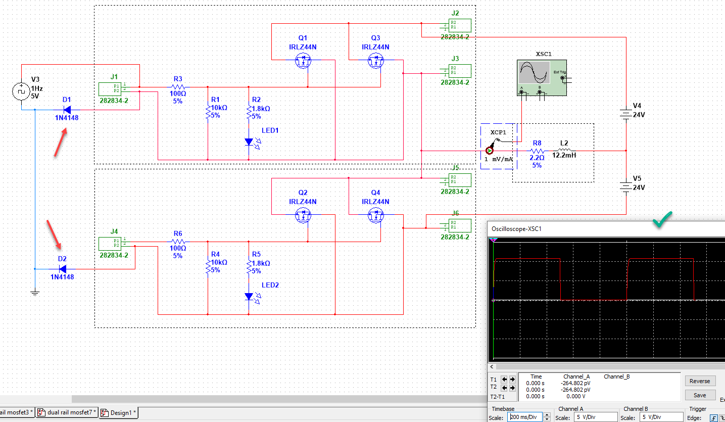
My first thought is to mitigate this with barrier diodes. However, I'm a novice with power electronics and dealing with the capacitance in the FETs, so in simulations, only a handful of switching diodes (like the 1N4148) are effective.

Common Zener diodes and Schottky diodes cause terrible waveforms in the oscilliscope, and the choice of diode varies the current reaching the load, so they are affecting activation of the FETs. It's a mess. This is the only reasonable simulation I could find:

Temporary solution

Questions:

  1. To avoid this becoming an X-Y problem, what is a better way to use these two n-MOSFET modules to establish a half H-bridge using a dual power supply?

  2. Is there a better way to isolate GND between the MCU and PSUs without optocouplers? Adding caps at different points along the GND segment adversely affects biasing of the FETs.

  3. Where would I even put freewheeling diodes? Is this a doomed design to begin with?


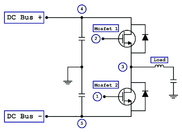
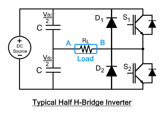
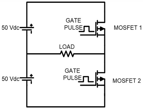
My inspiration comes from circuits like these:

Example 1

Example 2

Example 3

But, no one shows how to bias those gates - just "some pulse". Are these logic-level pulses? VDD/-VDD pulses? It's unclear how they avoid a short-circuit themselves.

\$\endgroup\$

1 Answer 1

3
\$\begingroup\$

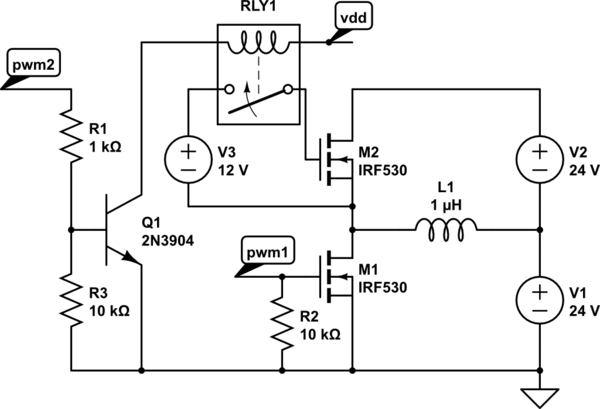
The design is doomed from the start. You need to provide for an isolated drive to the upper MOSFET of the half-bridge. You can probably get a proper half-bridge module, or you can use an opto-isolator and floating gate drive power supply for high side.

schematic

simulate this circuit – Schematic created using CircuitLab

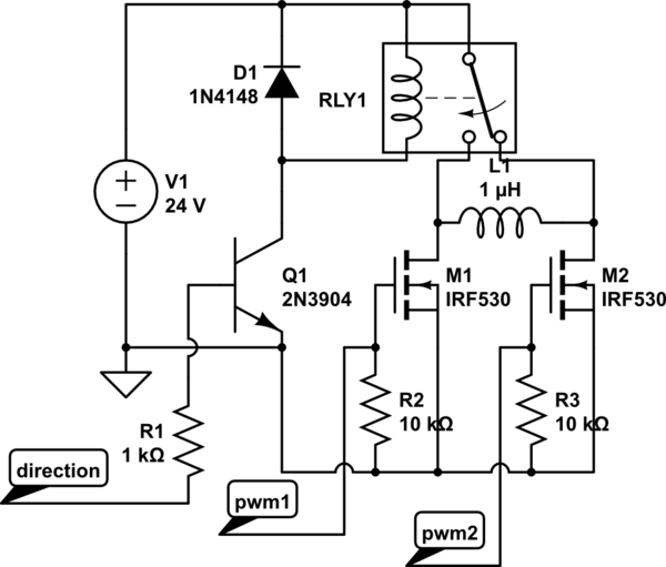
If you don't mind adding an SPDT relay, the circuit above might work. But it depends on how fast you need to switch direction. Otherwise you would need to implement a full bridge, or a half bridge with an isolated drive for the high side, and dual power supplies. The full bridge works with a single supply.

schematic

simulate this circuit

That is a half-bridge approach, which uses an isolated 12V gate supply and an opto-isolator (represented by RLY1 - didn't see a model in CircuitLab). Depending on switching speed, you may need a high speed optocoupler or an isolated high side MOSFET driver.

\$\endgroup\$
7
  • \$\begingroup\$ Proper half-bridge module or opto makes sense. I have a surplus of these nFET modules and several coils to build, so I am holding out for hope to use them, but if it is doomed, then it is. Thx. \$\endgroup\$
    – Drakes
    Commented Feb 13, 2023 at 21:57
  • \$\begingroup\$ Perhaps you can provide more details on the requirements for your "pulse motor". Is a half-bridge with both positive and negative drive actually needed? And it should not be too much problem to add a floating power supply and opto-isolator to use your existing modules. \$\endgroup\$
    – PStechPaul
    Commented Feb 13, 2023 at 22:14
  • \$\begingroup\$ Sure can. I have an electromagnet with 12.2mH and 2.2ohms. I'd like the microcontroller to turn it on with one polarity, then off, then on with the opposite polarity - with full possible current or PWM. I have two 24V/600W supplies, so I'd like to avoid using an H-bridge (requires sourcing all new parts, plus dealing with dead-time logic). The uC takes care of timing and Hall sensors. I have a surplus of these D4184 modules, and the uC, plus power diodes, so I'd love to make a half H-bridge work with these existing parts. Any ideas? (Thanks for being kind; power electronics are new for me) \$\endgroup\$
    – Drakes
    Commented Feb 13, 2023 at 23:29
  • \$\begingroup\$ This is a suggestion: Take a look at the BTS7960, it has all of what you need in one chip. They are also available as bridge modules which has two of these devices. I purchase them that way (about $6US) but use them as two independent 1/2 bridges. You might want to include a link to your Modules. The ones I found: protosupplies.com/product/d4184-mosfet-control-module have an opto isolator on board. You could copy the circuit and modify to your needs. \$\endgroup\$
    – Gil
    Commented Feb 14, 2023 at 2:22
  • \$\begingroup\$ @PStechPaul The second diagram is clever, enabling me to use these modules - let me digest and simulate it more to see the the switching speed will work. \$\endgroup\$
    – Drakes
    Commented Feb 14, 2023 at 22:47

Your Answer

By clicking “Post Your Answer”, you agree to our terms of service and acknowledge you have read our privacy policy.

Not the answer you're looking for? Browse other questions tagged or ask your own question.