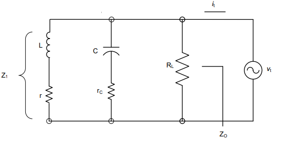
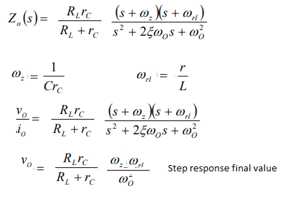
The output impedance of the buck converter operated in open-loop (no feedback) can be rearranged with a leading term representative of the resistance at dc (when the capacitor is open and the inductor shorted). I have looked at this transient response in may APEC 2012 seminar and the low-entropy expression is given below:

It is important to properly format the expression so that it gives insight on what contributors do. For instance, you can see that the inductive resistive drop \$r_L\$ affects the dc drop (the leading term \$R_0\$), while, together with the capacitor ESR, it damps the filter.
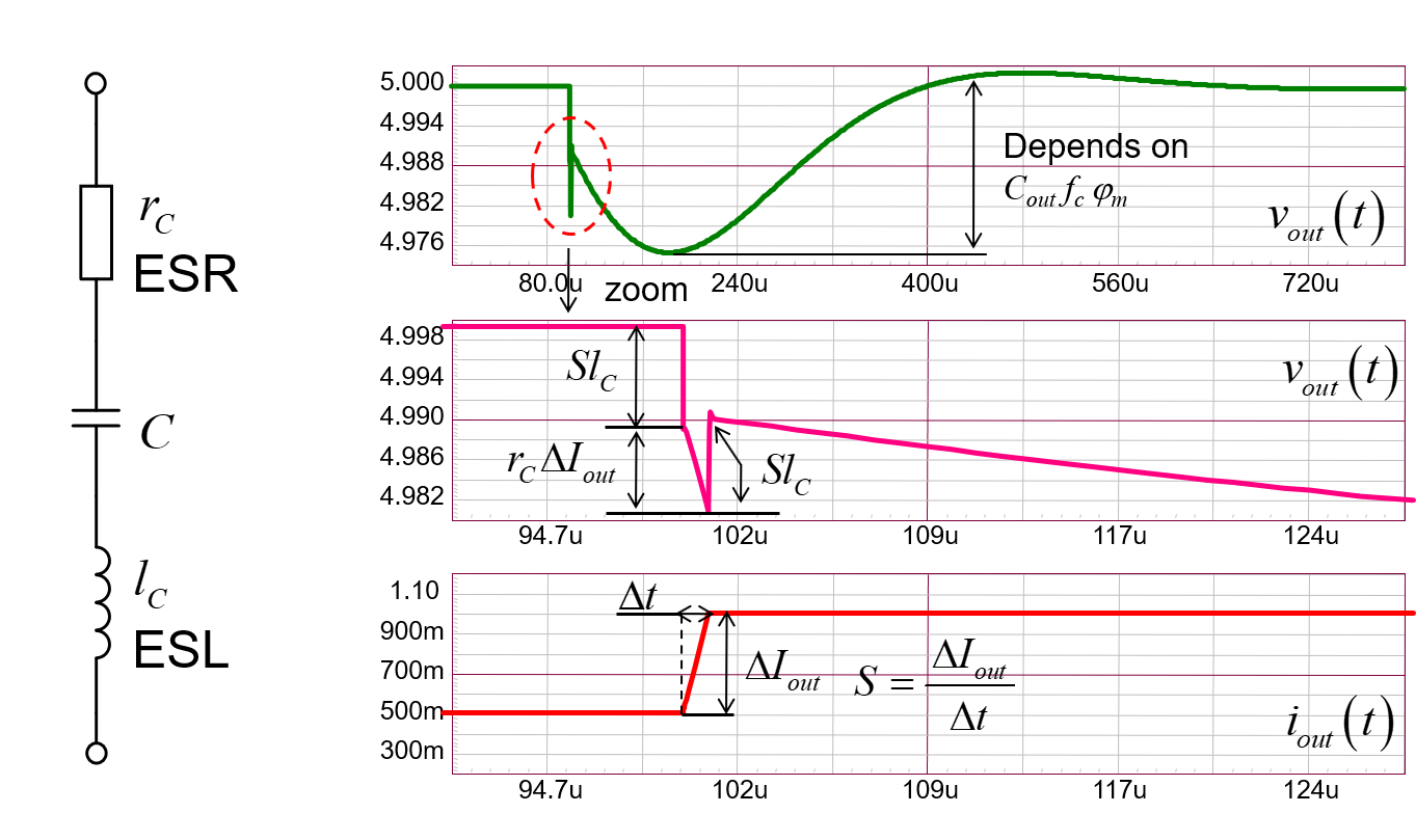
When you look at the transient response of the buck stage, the output capacitor dominates the response. However, this element is made of its capacitance term and two parasitics: an equivalent series resistance (ESR) noted \$r_C\$ and an equivalent series inductance (ESL) noted \$l_C\$. When you zoom on the response, this is what you see in simulation:

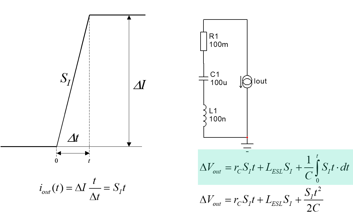
You have the contribution of the capacitance, the resistance drop and, finally, the inductive kick. This last one is often neglected in "slow" dc-dc converters but matters big time in high-speed dc-dc for motherboards for instance. The expression for the voltage is then the sum of these three voltages (see APEC 2009):

You consider the capacitor alone facing the transient step because even if you had an infinite bandwidth, the current cannot increase faster than what the inductor imposes cycle-by-cycle. The cap. alone delivers energy, giving time for the inductor current to build up.
As a quick summary, when selecting the capacitor, you do not think with the zero it introduces in terms of small-signal output impedance but more with the pure drop incurred by its ESR term alone.
As a side note, I have seen you have used the brute-force approach to derive the output impedance. You can check how the fast analytical circuits techniques or FACTs could lead you straight to the well-ordered answer without writing a single line of algebra. Check my APEC 2016 seminar on the subject that you can download from my web page.


