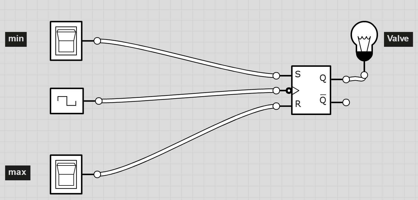
1
\$\begingroup\$

I need a circuit that can "simulate" opening/closing a valve for a water tank. The circuit has only 2 inputs, 'm' (minimum) and 'M' (Maximum), and an output 'V' (valve). The valve is only open if V= High(1). The tank has a floating water meter that goes up and down with the tank water level.

When the tank is emptying, as soon as the water meter reaches a certain level, minimum(m), the entry 'm' is Low and the valve should open to fill the tank. As soon as water meter reaches minimum(m) again in the rising direction, 'm' will become High but the Valve should remain open (=1). When the tank is filling, as soon as the water meter goes above a certain level Maximum(M), the entry 'M' is High and the valve should be closed. If the tank starts emptying again, 'M' will become Low but the valve should remain closed.

m=Low(0) and M=High(1) will never happen simultaniously.

I need to make two versions of this circuit: one using only NAND gates, and another using a JK Flip-Flop.

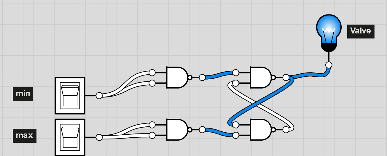
I tried using http://logic.ly/ for simulation purposes. One of the answers has a working NAND gate implementation, but I just can't wrap my head around the circuit with the JK flip-flop.
NAND gate schematic

\$\endgroup\$
2
  • \$\begingroup\$ I think it would be more helpful if you have posted he circuit you tried to make. \$\endgroup\$ Commented Dec 13, 2011 at 7:21
  • \$\begingroup\$ posted the circuit image... \$\endgroup\$
    – spacing
    Commented Dec 13, 2011 at 7:33

2 Answers 2

1
\$\begingroup\$

m=Low(0) and M=High(1) will never happen simultaniously

I didn't understand what you mean by above statement.

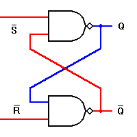
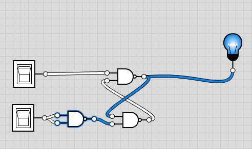
But what I understand is m and M will never be high at the same time. Since then, I think what you need is an SR Latch. It is easy to build an SR Latch using NAND gates. Here are the circuits I tried:

SR Latch Implementation

The Basic RS NAND Latch says:

SR Latch using NAND gates

Edit

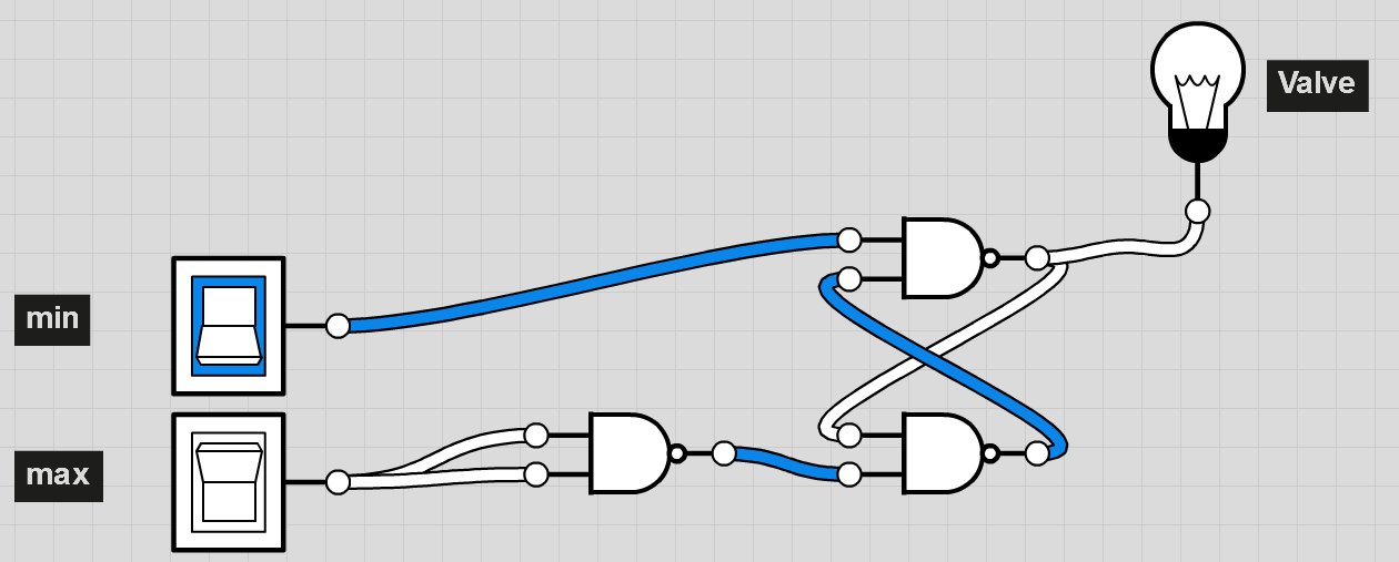
It is understood that when the water is at the minimum when min=0, so it is reversed. Just add a NOT gate after the min, and you can use the circuits above. A NOT gate could be build by a NAND gate by shorting its inputs.Here is the final circuit:

enter image description here

\$\endgroup\$
10
  • \$\begingroup\$ m=Low(0) and M=High(1) will never happen simultaneously because if the water level goes below a certain level for which m=0 then it can't be at the same time going over the Maximum limit M=1 \$\endgroup\$
    – spacing
    Commented Dec 13, 2011 at 7:41
  • \$\begingroup\$ I remember trying that last circuit, the problem is that when M(1), m(1) it is 1 and it should be 0 and the transition from that state to M(1), m(0) should return V=0 (HOLD the state) \$\endgroup\$
    – spacing
    Commented Dec 13, 2011 at 7:57
  • \$\begingroup\$ I figured the solution for the circuit with NANDs only, now I need it to do the same but with a flip flop JK which I tried before but have no idea how to do it link \$\endgroup\$
    – spacing
    Commented Dec 13, 2011 at 8:01
  • \$\begingroup\$ Have you tried the last circuit after "Edit"? I enter min(1) and max(1) and the valve (bulb) is off. M(1),m(0) means that the sensor for the maximum is true and the sensor is minimum is true. This doesn't seem logical to me, or I couldn't understand. \$\endgroup\$ Commented Dec 13, 2011 at 8:02
  • \$\begingroup\$ Just try refreshing the page next time =) \$\endgroup\$ Commented Dec 13, 2011 at 8:02
1
\$\begingroup\$

So you say you need to do it using a JK specifically, do you?

Ok.

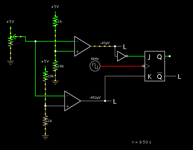
How does this look to you:

enter image description here

All the stuff on the left is to simulate your water tank - with the pot at the top the talk is full, and both "Sensors" are low.

As the level drops, the top sensor goes high. When it reaches the bottom, the bottom sensor goes high. When it rises, the bottom sensor immediately goes low. When it reaches the top, the upper sensor goes back to low.

Logic sequence table:

State    Upper    Lower    Desired result
-----------------------------------------
Full     L        L        L
Emptying H        L        L
Empty    H        H        H
Filling  H        L        H
Full     L        L        L

After the inverter you get:

State    Upper    Lower    Desired result
-----------------------------------------
Full     H        L        L
Emptying L        L        L
Empty    L        H        H
Filling  L        L        H
Full     H        L        L

An input of Low+Low to a JK holds the current state. Low+High is reset, and High+Low is set. So, at full the output is set. At empty, it is reset. All times in between it holds the current state.

Using the "inverted" output you get the signal you desire.

If the outputs to your sensors are active-low you can just move the inverter to the K input instead of the J and it should work fine.

\$\endgroup\$
4
  • \$\begingroup\$ He already found that out, @Majenko :) Look at the comments above. However, +1 for useful answer. \$\endgroup\$ Commented Dec 13, 2011 at 17:29
  • \$\begingroup\$ Half the comments were hidden, and I hadn't bothered to trawl through them. If it's not in an answer it doesn't exist. \$\endgroup\$
    – Majenko
    Commented Dec 13, 2011 at 18:08
  • \$\begingroup\$ lol, okay, no offense.. \$\endgroup\$ Commented Dec 13, 2011 at 18:20
  • \$\begingroup\$ this is ironic, lol. i got -15 just because i didn't add jk in my answer after the asker found it? \$\endgroup\$ Commented Dec 14, 2011 at 6:51

Your Answer

By clicking “Post Your Answer”, you agree to our terms of service and acknowledge you have read our privacy policy.

Not the answer you're looking for? Browse other questions tagged or ask your own question.