2
\$\begingroup\$

I understand (or at least think I understand) the math and calculation of RMS values and that it generally is used for representing equivalent power of non-DC circuits, like typical sinusoidal AC circuits, but it should also be useful in DC circuits for the same purpose.

There seems to be a discrepancy in the DC cases that I cannot find an answer for, and I feel like I must be missing something like it's so obvious that no reference material or classes mention it.

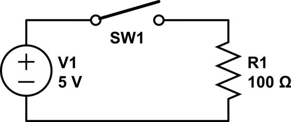
For example: the simple circuit below with 5 V DC supply and 100 Ω resistor that is switched at duty cycle D=75%.

schematic

simulate this circuit – Schematic created using CircuitLab

Assuming everything is ideal, what is the power dissipated by the resistor?

If \$P = V_{avg} × I_{avg}\$
then \$P = 5 V × 0.05 A × 0.75 = 0.1875 W\$, but the RMS value of the pulsed current waveform is \$I_{PK} × \sqrt{D}\$.

So if \$P = V_{RMS} × I_{RMS}\$ and \$I_{RMS} = 0.05 A × \sqrt{0.75}\$
then \$P = 0.217 W\$

  • Why the discrepancy?
  • The first number is correct, so what does that second number represent, or is it a meaningless value?
\$\endgroup\$
2
  • 3
    \$\begingroup\$ The first number is correct but this isn't: \$P=V_{avg}\times I_{avg}\$. \$\endgroup\$
    – Andy aka
    Commented Apr 19, 2023 at 7:24
  • \$\begingroup\$ according to the first equation it should be 5V x 0.75 x 0.05A x 0.75. You missed an extra 0.75. Actually in both cases you forgot about the fact the voltage is only on 0.75 of the time \$\endgroup\$ Commented Apr 19, 2023 at 9:09

4 Answers 4

6
\$\begingroup\$

To answer the titular question, what is RMS, it is the equivalent DC that would dissipate the same power in a resistive load. For instance, a 240V AC RMS sinusoid actually has peaks of ±340V, but it would dissipate the same power in a fixed resistance as a steady 240V DC. Likewise, 10A RMS of alternating current through some resistance would deliver the same amount of power as a constant 10A DC.

Because we are dealing with power, which is proportional to the square of voltage and current, giving rise to the famous power expressions \$\frac{V^2}{R}\$ and \$I^2R\$, we cannot rely on average values of current or voltage to perform power calculations, except under very particular circumstances. This becomes abundantly clear when we consider:

  • Current through a resistor in either direction causes the resistor to heat up (receive) energy, so power in the resistor is positive whether the current through it is positive or negative.

  • The average value of a sinusoidal signal (or any signal symmetrical above and below zero) is zero, but obviously an alternating voltage across or current through a resistor does not result in zero power being delivered to the resistor.

Now, onto your particular case:

Average current is \$I_{AVG} = 0.75 \times 50mA = 37.5mA\$.

Average voltage is \$V_{AVG} = 0.75 \times 5V = 3.75V\$.

You incorrectly said that power would be \$V_{AVG} \times I_{AVG}\$, but then you calculated that as:

$$ P = 5V \times 0.05A \times 0.75 = 0.1875W $$

That's the correct answer, for average power, but it's not \$V_{AVG} \times I_{AVG}\$!

$$ \begin{aligned} V_{AVG} \times I_{AVG} &= (5V \times 0.75) \times (50mA \times 0.75) \\ \\ &= (0.75)^2 \times 5V \times 50mA \\ \\ &= 140mW \end{aligned} $$

This is not the correct value for average power. The formula for apparent power is:

$$ P = V_{RMS} \times I_{RMS} $$

Note: for a purely resistive load, like yours, this expression for so-called "apparent power" does tell you the power dissipated in the load (as heat). However, as user @PeterGreen points out, it does not account for phase difference between current and voltage, and so cannot be used to determine the true, net power delivered to reactive loads. If the load is in any way able to store energy and/or return it to the source (such as capacitance or inductance), you must take an alternative approach to obtain true power.

For a rectangular signal, RMS value is not the same as the average value.

For some signal \$V(t)\$, its RMS is the square root of the average of \$V(t)^2\$. The "average of the square" is very different from the "square of the average", which is where I think you went wrong, but accidentally got the right answer.

For a rectangular signal with 75% duty cycle, RMS will be the Root of the Mean of the Square:

$$ \begin{aligned} V_{RMS} &= \sqrt{ \frac{75\% \times V^2 + 25\% \times 0^2}{100\%} }\\ \\ &= \sqrt{75\% \times V^2} \\ \\ &= \sqrt{75\% \times (5V)^2} \\ \\ &= 4.33V \end{aligned} $$

Similarly, RMS current will be:

$$ \begin{aligned} I_{RMS} &= \sqrt{75\% \times I^2} \\ \\ &= \sqrt{75\% \times (50mA)^2} \\ \\ &= 43.3mA \\ \\ \end{aligned} $$

To find power, we have:

$$ \begin{aligned} P &= V_{RMS} \times I_{RMS} \\ \\ &= 4.33V \times 43.3mA \\ \\ & = 187.5mW \end{aligned} $$

or

$$ \begin{aligned} P &= \frac{{V_{RMS}}^2}{R} \\ \\ &= \frac{(4.33V)^2}{100\Omega} \\ \\ & = 187.5mW \\ \\ \end{aligned} $$

or

$$ \begin{aligned} P &= {I_{RMS}}^2R \\ \\ &= (43.3mA)^2 \times 100\Omega \\ \\ & = 187.5mW \\ \\ \end{aligned} $$

or, average power. Remembering that \$P_{100\%} = 5V \times 50mA = 250mW \$, average power at 75% duty cycle will be:

$$ \begin{aligned} P_{75\%} &= 75\% \times P_{100\%} \\ \\ &= 0.75 \times 250mW \\ \\ & = 187.5mW \\ \\ \end{aligned} $$

If you look closely, this last calculation is what you "accidentally" performed to arrive at the correct answer!
\$\endgroup\$
1
  • \$\begingroup\$ BTW P=Vrms×Irms is only true if V is proportional to I (which is true in the OP's circuit but not always). \$\endgroup\$ Commented Apr 19, 2023 at 21:00
6
\$\begingroup\$

Follow along:

$$\begin{align*} \overline{P}&=f\int_{0}^{\frac{1}{f}} \frac{V_t^2}{R}\:\text{d}t\\\\&=\frac{f}{R}\int_{0}^{\frac{1}{f}} V_t^2\:\text{d}t\\\\&=\frac{f}{R}\left\{\int_{0}^{\frac{0.75}{f}} V^2\:\text{d}t+\int_{0}^{\frac{0.25}{f} } 0\:\text{d}t\right\}\\\\&=\frac{f\,V^2}{R}\int_{0}^{\frac{0.75}{f}} \text{d}t\\\\ &=\frac{f\,V^2}{R}\left[\vphantom{\frac{f\,V^2}{R}\int_{0}^{\frac{0.75}{f}} \text{d}t}t\right]_0^\frac{0.75}{f}\\\\ &=\frac{f\,V^2}{R}\left[\vphantom{\frac{f\,V^2}{R}\int_{0}^{\frac{0.75}{f}} \text{d}t}\frac{0.75}{f}-0\right] \\\\ &=\frac34\frac{V^2}{R}=\frac{\left[\frac{\sqrt{3}}{2}V\right]^2}{R} \end{align*}$$

From this, it's easy to see that \$V_{_\text{RMS}}=\frac{\sqrt{3}}{2}V\$ for a 75% duty cycle. Here, at 75% duty, \$V_{_\text{RMS}}\approx 4.33\:\text{V}\$.

The same process using \$I_t\$ instead of \$V_t\$ would get you to the exact same result.

$$\begin{align*} \overline{P}&=f\int_{0}^{\frac{1}{f}} I_t^2\,R\:\text{d}t\\\\&=f\,R\int_{0}^{\frac{1}{f}} I_t^2\:\text{d}t\\\\ &=f\,R\left\{\int_{0}^{\frac{0.75}{f}} I^2\:\text{d}t+\int_{0}^{\frac{0.25}{f} } 0\:\text{d}t\right\}\\\\ &=f\,I^2\,R\int_{0}^{\frac{0.75}{f}} \text{d}t\\\\ &=f\,I^2\,R\left[\vphantom{\frac{f\,V^2}{R}\int_{0}^{\frac{0.75}{f}} \text{d}t}t\right]_0^\frac{0.75}{f}\\\\ &=f\,I^2\,R\left[\vphantom{\frac{f\,V^2}{R}\int_{0}^{\frac{0.75}{f}} \text{d}t}\frac{0.75}{f}-0\right] \\\\ &=\frac34 \,I^2\,R=\left[\frac{\sqrt{3}}{2}I\right]^2\,R \end{align*}$$

So \$I_{_\text{RMS}}=\frac{\sqrt{3}}{2}\frac{V}{R}\$ for a 75% duty cycle. Here, at 75% duty, \$I_{_\text{RMS}}\approx 43.3\:\text{mA}\$.

Just follow the same process to get the RMS values regardless of repeating waveform.

Take note that \$4.33\:\text{V}\,\cdot\,43.3\:\text{mA}\approx 187.5\:\text{mW}\$, also as expected.

\$\endgroup\$
2
  • 3
    \$\begingroup\$ \$\frac{\sqrt{3}}2\$ is better known as \$\sqrt{0.75}\$ for the purposes of this question \$\endgroup\$ Commented Apr 19, 2023 at 10:14
  • \$\begingroup\$ @user253751 I much prefer my use of integers. So do some mathematicians. \$\endgroup\$ Commented Apr 19, 2023 at 12:23
4
\$\begingroup\$

" Ipk * sqrt(D), so if P= Vrms * Irms and Irms= 0.05A * sqrt(0.75) then P= 0.217W"

Vrms = Vpk * \$\sqrt{0.75}\$

Irms = Ipk * \$\sqrt{0.75}\$

P = Irms * Vrms = Vpk*Ipk * 0.75 = 0.1875W

\$\endgroup\$
2
  • \$\begingroup\$ True in this case (resistive load), so V and I have the same shape. Not necessarily true in general if the load involved some L or C components as well as resistors. That might be a good test for whether a certain way of thinking about the problem is useful. (I think Andy Aka's answer is the most intuitive: power is applied 75% of the time, and when it's on it's Vpk * Ipk.) \$\endgroup\$ Commented Apr 20, 2023 at 1:08
  • \$\begingroup\$ @PeterCordes Yes, of course, and that's the way I would calculate it, but I wanted to apply the sqrt(D) formula the OP has. \$\endgroup\$ Commented Apr 20, 2023 at 2:15
3
\$\begingroup\$

If \$P=V_{avg}\times I_{avg}\$

It doesn't unless V and I are constant. Calculating power is quite simple: average power.

When the switch is closed the power is \$\frac{volts^2}{ohms}\$ = 250 mW.

The power is present for only 75% of the time hence, the average power is 187.5 mW.

if \$P=V_{RMS}×I_{RMS}\$ and \$I_{RMS}=0.05A×\sqrt{0.75}\$ then P=0.217W

It doesn't because you assumed the voltage applied to the resistor was always 5 volts and clearly it isn't; it has the same "shape" as the current.

\$\endgroup\$
0

Your Answer

By clicking “Post Your Answer”, you agree to our terms of service and acknowledge you have read our privacy policy.

Not the answer you're looking for? Browse other questions tagged or ask your own question.