0
\$\begingroup\$

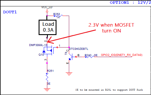
We have a DOUT current sink circuit in one of our designs. We found that there is a 2.3 V drop across the drain to source when the MOSFET is turned ON.

As per the MOSFET's datasheet, RDS(on) is 99 mΩ (max). Considering this resistance and a load current of 0.3 A, the drop should be 0.027 V, but it's more than that.

What could be the issue? How to resolve it? VCC_LD is 12V.

enter image description here

\$\endgroup\$
3
  • 2
    \$\begingroup\$ What's your gate-source voltage? \$\endgroup\$
    – 11011100
    Commented Apr 19, 2023 at 8:08
  • \$\begingroup\$ We have measured the gate voltage i.e 58.7mV when MOSFET is turn ON \$\endgroup\$ Commented Apr 19, 2023 at 8:29
  • 1
    \$\begingroup\$ Looking at the datasheet the Gate Voltage needs be at least 2V below the source. \$\endgroup\$
    – 11011100
    Commented Apr 19, 2023 at 9:08

1 Answer 1

6
\$\begingroup\$

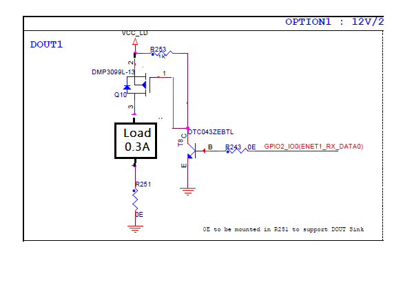
Since Q10 is a PMOS and you have used it on the low side, you will have a drop across it equal to the Vgs of the transistor. For small currents, it will be close to VTH which is ~1.5 V typ. As current increases, more VGS is needed and hence more drop.

You should use Q10 on the high side, i.e., above the load to avoid this drop as shown below

enter image description here

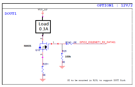
Other option is to use an NMOS on the low side and invert its gate control. Make sure that you use an NMOS which has a low enough RDS when the GPIO is driving high on the NMOS gate.

enter image description here

\$\endgroup\$
6
  • \$\begingroup\$ As My understanding, the P-MOSFET gate is needed negative voltage for complete conduction...since we are providing a voltage near Zero i.e 58.7mV, this would reason for more RDS than mentioned in the datasheet value. This may be the reason for the voltage drop I guess, is this correct? With the existing circuit, How can I eliminate this voltage drop? is there any way? \$\endgroup\$ Commented Apr 19, 2023 at 11:21
  • \$\begingroup\$ @Chitharanjan, I am not sure you understood my answer. So, I have added some diagrams to help you. This is not an RDS issue that you are facing. The drop is because of VGS limitation. In this configuration, gate = 0V. So, source cannot go lower than say 2V because you need a VGS for the PMOS to turn ON. \$\endgroup\$
    – sai
    Commented Apr 19, 2023 at 11:43
  • \$\begingroup\$ Is there any way to reduce the 2.3V drop in the existing design, without moving the MOSFET higher side? The reason of connected the MOSFET on the higher side because Since this MOSFET circuit is working as a sinking circuit other vice it act as source circuit if we add the MOSFET in lower side \$\endgroup\$ Commented Apr 20, 2023 at 10:51
  • \$\begingroup\$ @Chitharanjan, no other clean option other than the above 2 ideas. One crazy idea would be to short out the PMOS if you can keep the load ON always. \$\endgroup\$
    – sai
    Commented Apr 20, 2023 at 11:08
  • \$\begingroup\$ OK understood, can you please elaborate a little more on the PMOS VGS limit for understanding the working? \$\endgroup\$ Commented Apr 20, 2023 at 11:56

Your Answer

By clicking “Post Your Answer”, you agree to our terms of service and acknowledge you have read our privacy policy.

Not the answer you're looking for? Browse other questions tagged or ask your own question.