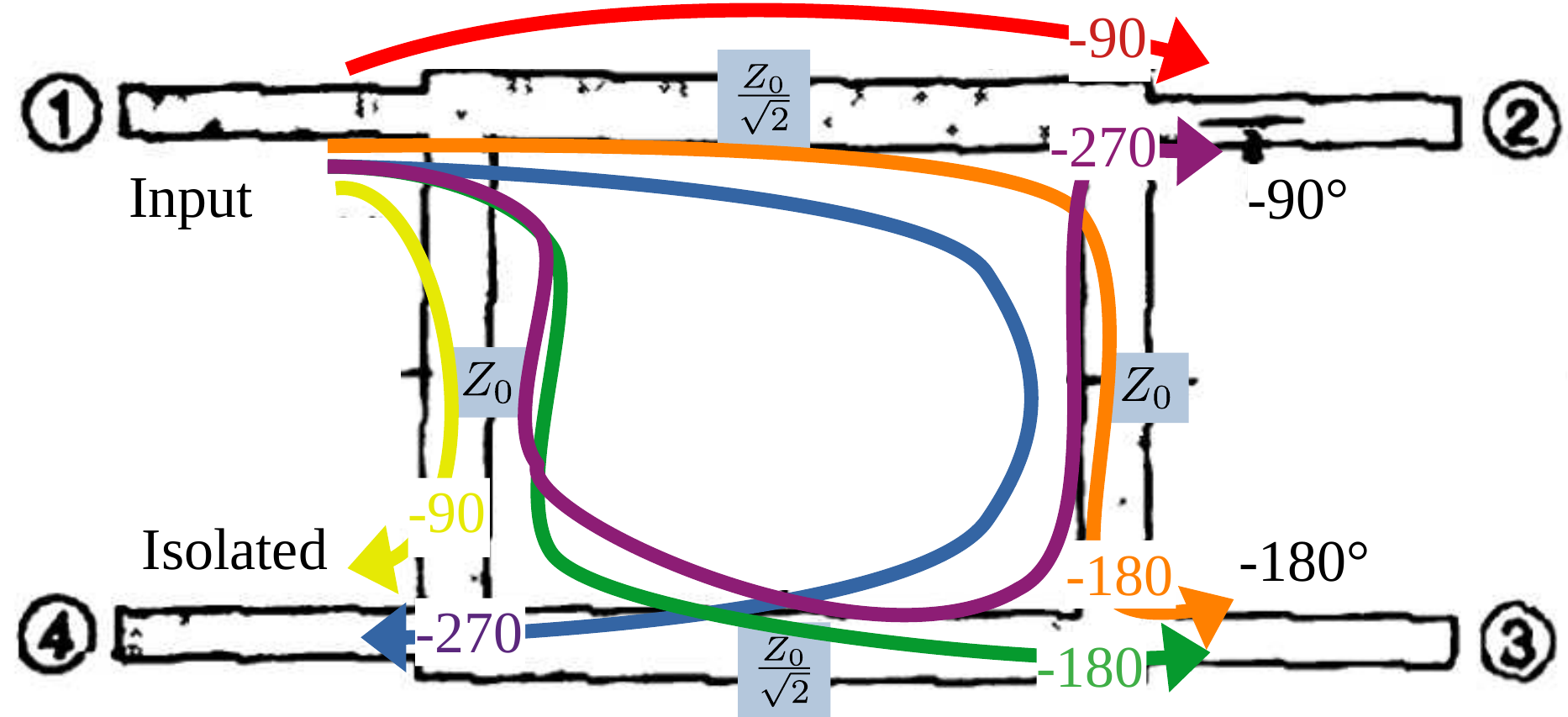
according to "Foundations for Microwave Engineering" by Robert E. Collin, Lumped Element Quadrature Hybrids" by D. Andrews and several others this is what a Quarter-wave branch line hybrid looks like:

Assuming input is at port 1, port 2 is supposed to have a -90° phase shifted signal, port 3 is supposed to have a -180° phase shifted signal and port 4 is supposed to be isolated i. e. having no signal at all.
I go along with port 3: both signal paths (right-down as well as down-right) encounter the same phase delay of -180° and interfere constructively at port 3 thus creating a -180° phase shifted signal.
I also agree with port 4 being isolated: one signal path (down) shifts the signal by -90° while the other signal path (right-down-left) shifts the signal by -270°. This leads to two signals out of phase by 180° canceling each other at port 4.
My problem is with port 2: while it is supposed to provide a -90° phase shifted signal, my reasoning is that, similar to port 4, one signal is -90° phase shifted while the other signal is phase shifted by -270° and both signals cancelling each other out.
What is the deal here? What am I missing? And why are the horizontal lines of the hybrid supposed to have that specific impedance ratio of those vertical lines? Whats up with that?
