5
\$\begingroup\$

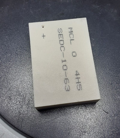
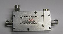
I've bought a few 50MHz-6GHz directional couplers (SEDC-10-63+,) each for 75$. Here is a picture of this expensive coupler:

directional coupler

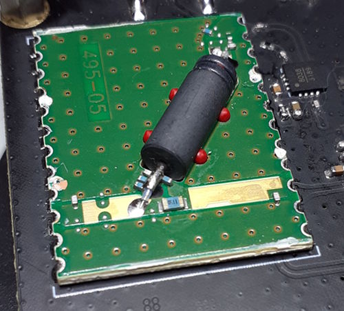
Unfortunately one of these couplers was not working from the beginning so I decided to take the cover off and get a glimpse of the insides.

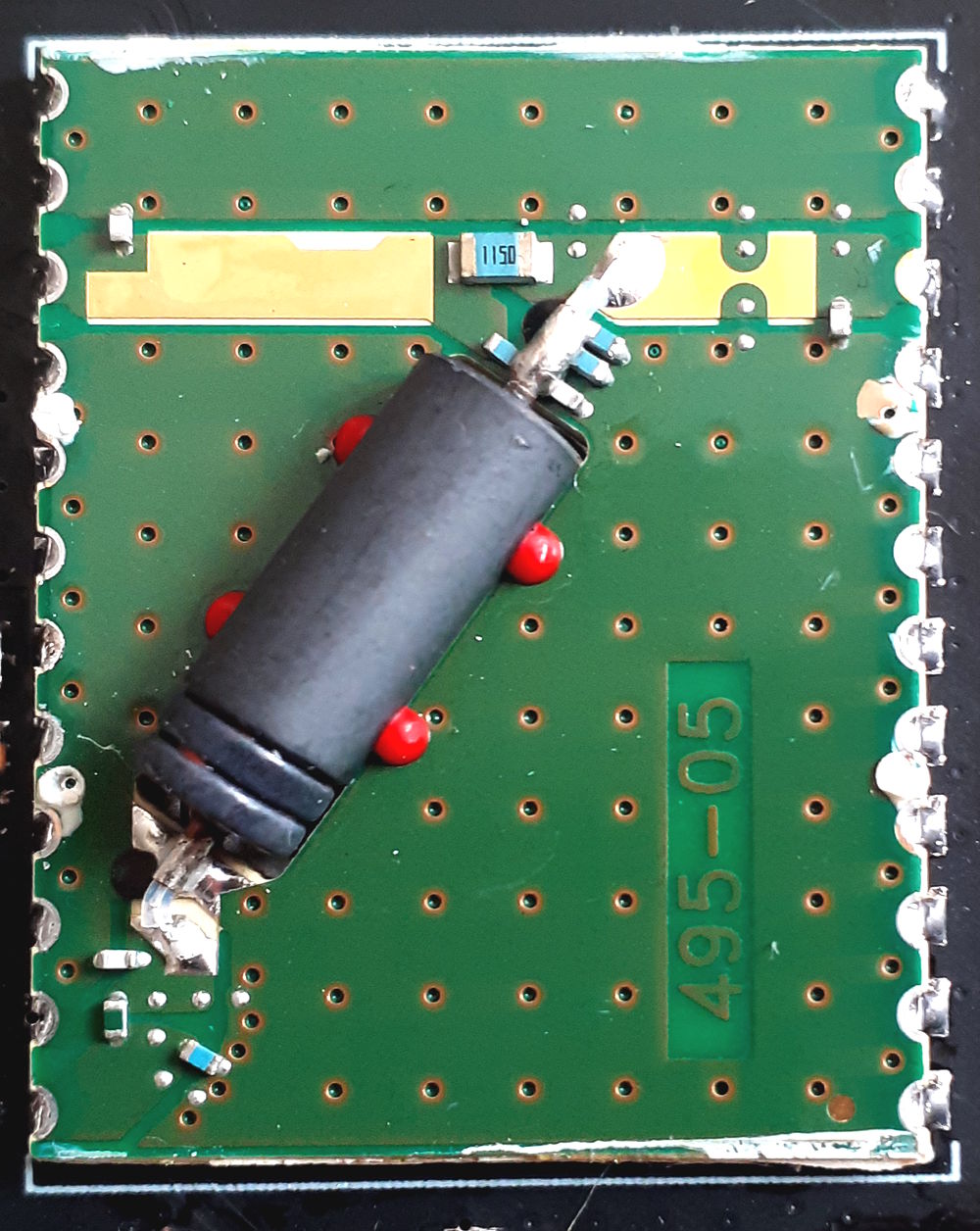
The problem is I cannot understand what this big black component is (probably a ferrite,) what it does, and how it contributes to the coupling or directivity.

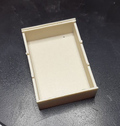
I also wondering if the cover is anything more than a simple cover. The top cover feels like a plastic but sounds like a ceramic object.

Coupler Inside

enter image description here enter image description here

Cover

enter image description here enter image description here

Update 1

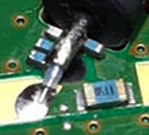
What does this 1150 component do? connect output to the coupled port? Doesn't this decrease the directivity? enter image description here
\$\endgroup\$
4
  • \$\begingroup\$ Your data sheet link seems missing pages. \$\endgroup\$
    – Andy aka
    Commented Jan 9, 2020 at 18:50
  • \$\begingroup\$ that black component looks like a ferrite bead ... can you post a sideways view of the two grooves on the far end? \$\endgroup\$
    – jsotola
    Commented Jan 9, 2020 at 19:23
  • \$\begingroup\$ @Andyaka Thanks Andy, Datasheet link updated \$\endgroup\$
    – pazel1374
    Commented Jan 10, 2020 at 6:31
  • \$\begingroup\$ @jsotola Requested image added, Thanks in advance \$\endgroup\$
    – pazel1374
    Commented Jan 10, 2020 at 7:07

2 Answers 2

5
\$\begingroup\$

The big black ferrite bead is to get the coupler working down to 50MHz.

The 6GHz end of operation is taken care of by the coax line acting as a straightforward transmission line balun. However, a bare line will only work well down to a frequency at which it's a quarter wave long.

Below that frequency, the ferrite raises its common mode impedance and starts to make the two line conductors, inner and outer, behave like two windings in a transformer. This pushes the performance down in frequency, limited only by the permeability, quality and dimensions of the ferrite.

Part of the 'secret sauce' that the manufacturers have to stir into it to get it to work is to handle the frequency response wrinkles in the crossover region between the transmission line balun and the transformer balun operation. There seem to be a lot of additional components scattered around inside the package, some of which have probably been added after experiment to flatten and tame the response.

You might want a better link to the datasheet

\$\endgroup\$
2
  • \$\begingroup\$ Thanks for your answer, can you show your points on the images, also can you declare your thought about cover and if it do anything with the ferrite \$\endgroup\$
    – pazel1374
    Commented Jan 10, 2020 at 7:11
  • \$\begingroup\$ By "two line conductors" do you mean the two conductors of the coax? Why does making it behave like a transformer push performance down into lower frequencies? \$\endgroup\$
    – DKNguyen
    Commented Jan 14, 2020 at 20:42
4
\$\begingroup\$

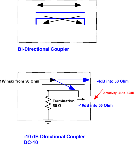
It's a precision microwave "hybrid" ferrite transformer with 50 Ohm resistor stable to 6GHz with 1 Watt RF maximum input.

This is basically a 6dB directional coupler with 4dB insertion loss, so essentially a DC-10.

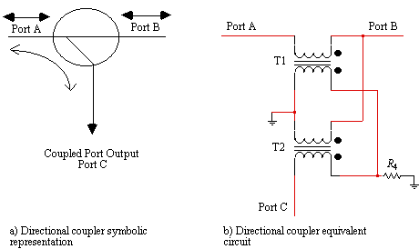
Let's review a bi-directional coupler schematic which is a fractional RF splitter with one port not used and terminated internally.

enter image description here

schematic

simulate this circuit – Schematic created using CircuitLab

Teflon (Rogers subst.) Transmission Losses are more significant when you span > 2 decades to 6 GHz

When output is disconnected or RL=0 dB , -10dB power is reflected back into internal termination.

Given the extreme sensitivity to material quality and tolerances for high Return loss values >40dB, $50 is cheap compared the precision aluminum cavity versions. enter image description here

Again enter image description here

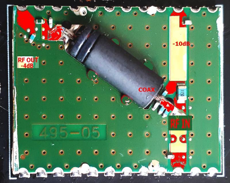
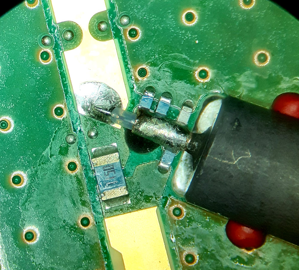
I poured Red to highlight the signal ports with that were hidden from green solder-mask that otherwise covers the green signal ground plane.

Many SMD passive components are used to normalize the 50 Ohm impedance and balance the ports to ground and couple to output port for directivity.

The PCB is milled out to fit the component flush and held in place with 4 red PU plastic drops. The ends are rigid coaxial tubes with RF plastic insulation. It is hard to imagine this 3 port DC -10 has a clever coaxial splitter port at one end that has up to 40 db directivity at 5GHz but rated at 23 dB min. enter image description here This was just a quick SWAG.

\$\endgroup\$
5
  • \$\begingroup\$ Thanks for your answer but the black component seems to have only two port, I updated the question and add a new photo for you \$\endgroup\$
    – pazel1374
    Commented Jan 10, 2020 at 7:13
  • 2
    \$\begingroup\$ The photo would need to be 10x to see the 2 ports splitting out of one end using a coaxial port shield and centre conductor. Various film caps and resistors are visible. Not your standard layout. \$\endgroup\$
    – D.A.S.
    Commented Jan 10, 2020 at 7:33
  • \$\begingroup\$ Thanks, you are right. Now that I inspect tbe component I saw that it actually have 4 ports. BTW can you explain more what do you mean by "It is hard to imagine this 3 port DC -10 has a clever coaxial splitter port at one end that has up to 40 db directivity at 5GHz but rated at 23 dB min"? \$\endgroup\$
    – pazel1374
    Commented Jan 10, 2020 at 11:57
  • \$\begingroup\$ Your pinout doesn't match the datasheet, also here the correct pinout is shown xmicrowave.com/product/xm-b7j3-1212d \$\endgroup\$
    – Damien
    Commented Jan 15, 2020 at 12:17
  • \$\begingroup\$ pazel, just the sensitivity of -40dB @ 5 GHz due to component soldering , orientation and even the slightest of melting coax inner clear dielectric with a very low melting point , imagine how that would scatter the sweeps (pun intended) ... greatly that far down. \$\endgroup\$
    – D.A.S.
    Commented Jan 15, 2020 at 14:32

Your Answer

By clicking “Post Your Answer”, you agree to our terms of service and acknowledge you have read our privacy policy.

Not the answer you're looking for? Browse other questions tagged or ask your own question.