1
\$\begingroup\$

I would like to create a program that uses a Raspberry Pi Pico, this four-digit seven-segment display, SG90 micro servos, and one of these buttons.

My idea is that every time the button is depressed, it adds 1 minute to a timer, which is visible on the display. Once the button is held down, the timer is started at the currently displayed time. Once the timer ends an SG90 servo will move.

Does anyone know what pins the different parts need to connect to, since I can't find any instructions online? Any and all help is greatly appreciated!

I couldn't figure out how to connect the display, since I did not purchase one of the more expensive 4 pin displays - which appear to be all that the tutorials are about (the TM1637).

\$\endgroup\$

2 Answers 2

1
\$\begingroup\$

Since your "display" (which is actually not a display but a 4x8 LED matrix) doesn't have any controlling circuit, you'll have to controll it "manually". You can connect 8 anodes of your LEDs to any 8 GPIOs of RPi and use 4 more GPIOs to controll common cathodes (not directly but by using transistors or something like ULN2003 driver) Then you'll need to find or write your own code that will controll the segments to display what you need. It migh be not as straightforward as you expect if you're new to this. Google "how to control led matrix with arduino / rpi"

For your servo & button you can also connect them to any free GPIO. Dont forget the pull-up for the button and cofigure it as input. For the servo you need to use servo library and tell it on which pin you've connected the servo.

As a side note, raspberry pi is total overkill for this kind of task. Arduino would be completely enough here and likely even easier to work with / find tutorials.

\$\endgroup\$
1
\$\begingroup\$

An LED segment is actually a collection of LEDs.

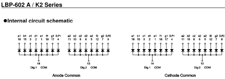
for example, I choose a LBP-602MA2 and the internal circuits are as follows:

enter image description here

According to this circuit diagram, this model provides two versions of the common terminal. pin 14 or 13 provide common power to each LEDs. You'll be able to complete the circuit. This will turn on the LED at that location.

so, You can also control it by placing the GPIO pin output and resistor if you want. (but not recommended. to do this, you need to know the power current specification of the GPIO. Segment LED drivers give you no worries about this.)

\$\endgroup\$
0

Your Answer

By clicking “Post Your Answer”, you agree to our terms of service and acknowledge you have read our privacy policy.

Not the answer you're looking for? Browse other questions tagged or ask your own question.