1
\$\begingroup\$

So I am trying to control 28 servos to make a 7 segment display clock with moving segments. Using a single signal line and 4 p channel MOSFETs and 7 n channel MOSFETs and a binary to 7 segment decoder(cd4511).

Link to video

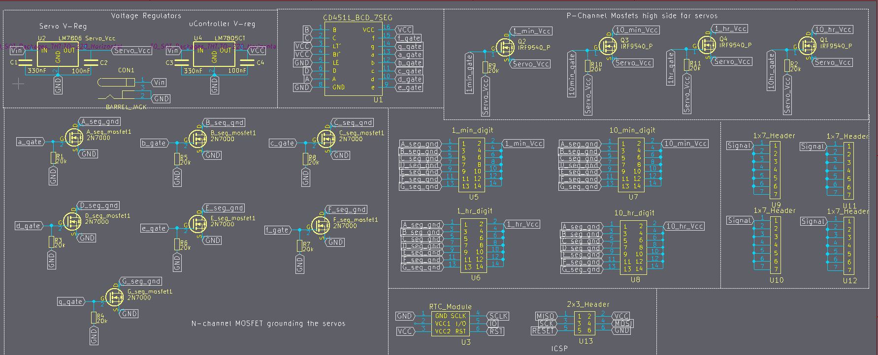
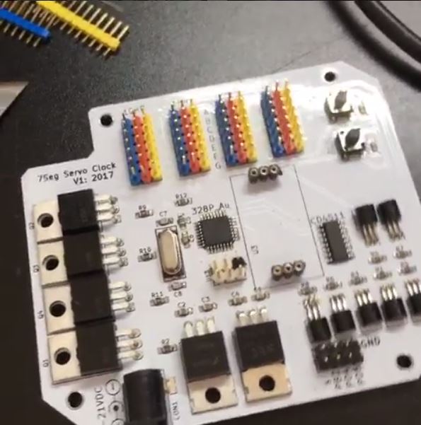
Below is a sample schematic and after that the real schematic, I know both MOSFETs show up as N-channel but the end product has the proper P channels with correct pinout, you can also view the actual board, the module in the middle is for an RTC, next to barrel jack is Vreg for the micro controller and Vreg for the servos Sample Schematic enter image description here enter image description here
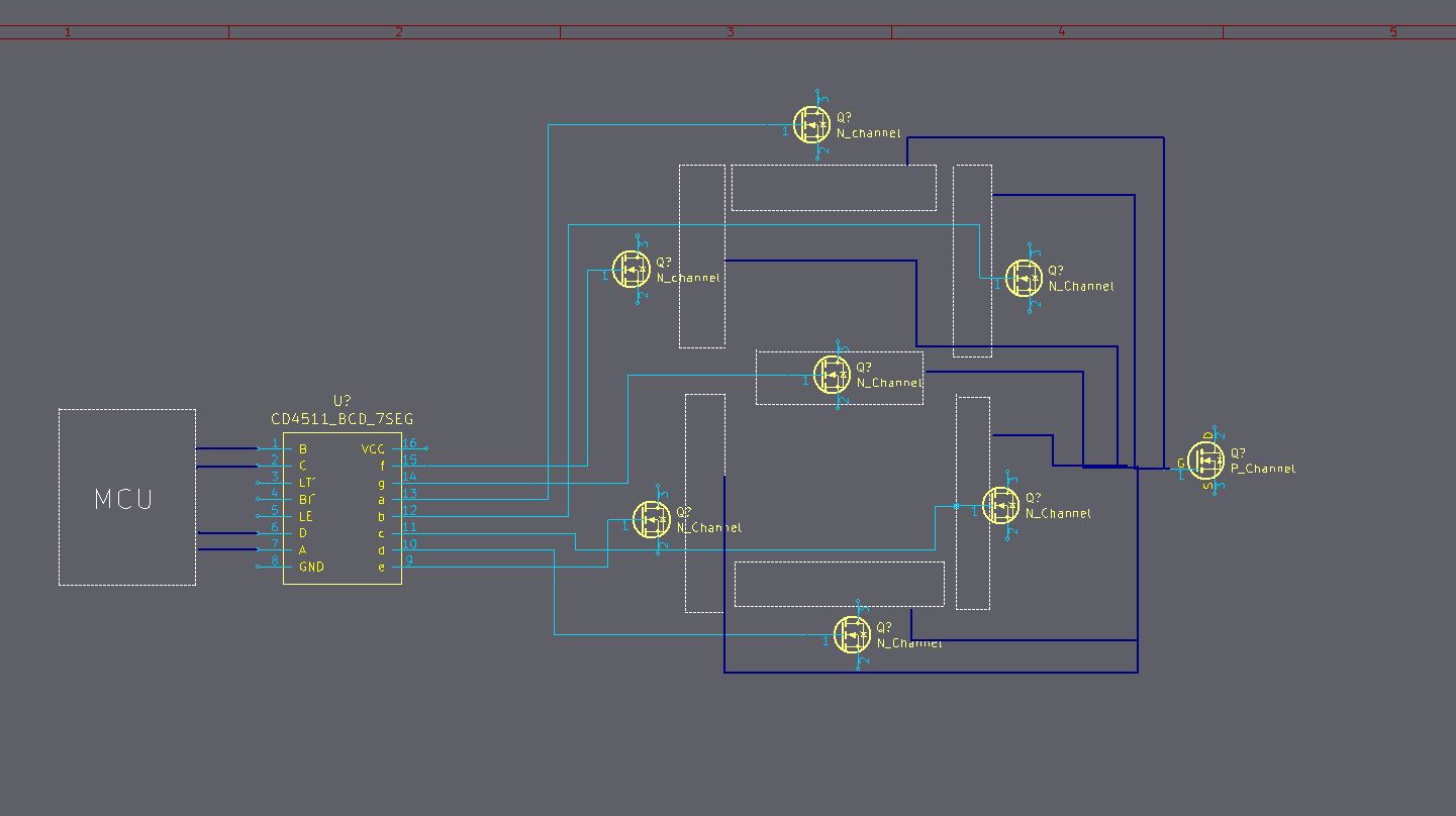
Look at the images provided for reference in the real schematic because in my schematics I use labels and not real lines so I am not sure if that will help you understand the circuit, so that's why I drew a sample one with lines. I also have a video link of one of the digits working as expected but the issue arises once I connect the rest of the digits.

First, there s a CD4511 Binary to 7 Segment decoder, this will take 4 inputs ABCD, A being least significant bit, I drive those pins high and low to make a binary number between 0 and 9. The IC then drives the corresponding output lines (ABCDEFG)high to make that number appear on a segment display. However I am not using it to drive an LED Display, instead, I am driving MOSFETs which are acting as LOW side switches for the Servos, All 28 Servos! However not all 28 are actually on because for every 7 servos (hence one digit) I have a P-channel MOSFET as a High side switch, that I control with the microcontroller, So when the time changes I only change one digit (7 servos) at a time and never all 28 servos.

So for example , If I want the first digit (the ones digit for the Minute) to display a 3 , i would set A and B high on the CD4511 chip, this would then through the N-channel MOSFETs provide the low side for the servos, then I would also activate the P_channel MOSFET via the microcontroller to only provide the high side of the first 7 servos which correspond to the ones digit of the minutes. So now those 7 servos are "on" and I give them the PWM signal to move their arms to the desired position that will reveal the segment like in the video. In theory the rest of the servos are not ON because the CD4511 decoder is not turning their MOSFETs on and I also have not turned the high side MOSFET ON for them either... the problem is that they DO move and the ones that I want to move don't move properly!!! and not to the position set by the PWM signal but just erratically, Now If I unplug all the servos and only leave 7 servos plugged in, doesn't matter what 7 servos it is but so long as I only work with one digit everything works fine like in the video, the problems are when everything is plugged in....I just can't figure out why? PWM signal looks clean in the scope.

\$\endgroup\$
9
  • \$\begingroup\$ what justifies a down vote? Did I ask improperly? Please correct me so that I may ask my questions as they should be asked, otherwise I will never learn. \$\endgroup\$ Commented Jul 26, 2017 at 4:55
  • \$\begingroup\$ I don't know what motivated someone to downvote. Seems like a fair question to me. Anyway, coming to point. Can you share more details, I mean the MOSFET number and the servo details? Are all the servos powered via 7805 IC? \$\endgroup\$
    – Mayank
    Commented Jul 26, 2017 at 5:09
  • 2
    \$\begingroup\$ Your servos need VCC and ground all the time. Switching VCC on and off will upset the servo internal control. All you need to do is control the PWM signal to each segment for the digits. Since you actually only have two positions for each servo, you could simply switch the on/off PWM to each segment from simple digital ports and run two PWMs as interrupt driven activation. You don't need a decoder at all...this could all be simply done in software. \$\endgroup\$ Commented Jul 26, 2017 at 5:10
  • \$\begingroup\$ Just for better understanding and being able to provide a better solution, can you explain why you chose this design? I mean is it that your application is very power sensitive? It's because I think a better solution would be to use just analog multiplexer in cascade mode and just 5 mux should make the circuit work. Although I am not sure about it. \$\endgroup\$
    – Mayank
    Commented Jul 26, 2017 at 5:17
  • \$\begingroup\$ I agree with @JackCreasey, the decoding could be simply done by controller and decoder is not necessary at all. \$\endgroup\$
    – Mayank
    Commented Jul 26, 2017 at 5:19

1 Answer 1

1
\$\begingroup\$

In theory the rest of the servos are not ON because the CD4511 decoder is not turning their MOSFETs on and I also have not turned the high side MOSFET ON for them either... the problem is that they DO move

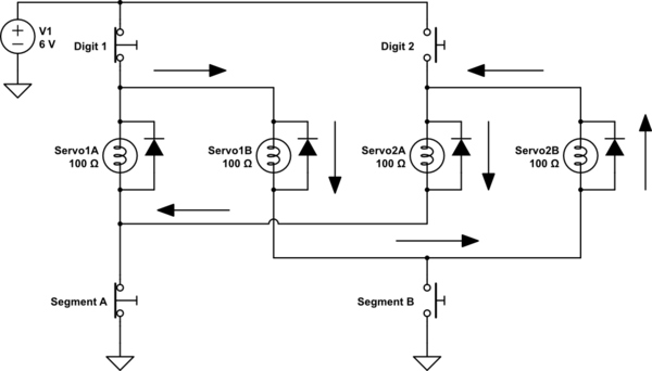
I suspect this is caused by caused by power backfeeding through the 'unpowered' servos. Unlike LEDs which block reverse current, RC servos have a control IC (and perhaps a discrete H-bridge) which look like a forward-biased diode when connected with reverse polarity.

Consider the simplified circuit below with just 2 segments and 2 digits. The digit and segment FETs are modeled as switches, and servos as lamps with parasitic reverse diodes:-

schematic

simulate this circuit – Schematic created using CircuitLab

Digit 1 and Segment A are switched on, supplying power to Servo1A. But there is another path - shown by the arrows - through Servo1B, Servo2B (reversed), and Servo2A. Servo2B will drop about ~0.6V, leaving ~5.4V to be shared between Servo1B and Servo2A. Either or both of these servos may move if their share of the voltage is sufficient to operate them.

To prevent backfeeds you could put a diode in series with the positive lead of each servo. However it might be better to switch the servos' signal inputs rather than their power supplies. Multiplexing the servo signals would also prevent possible problems caused by signals being fed into unpowered servos with floating grounds.

\$\endgroup\$

Your Answer

By clicking “Post Your Answer”, you agree to our terms of service and acknowledge you have read our privacy policy.

Not the answer you're looking for? Browse other questions tagged or ask your own question.