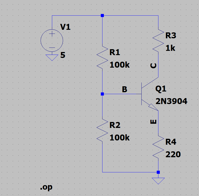
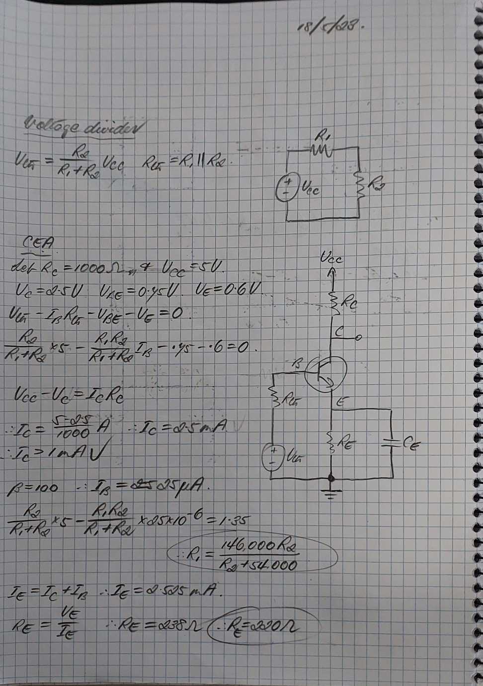
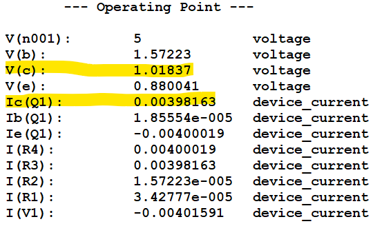
I'm trying to design this common emitter amplifier to have a Q-point of \$(V_C=2.5 V, I_C = 2.5 mA)\$. According to my calculations (see below), if I were to use \$R_2 = 100 k\Omega\$, I should also use \$R_1 = 100 k\Omega\$ to achieve this. However, when I ran a DC analysis of my circuit on LTspice, it said that my Q-point was at \$(V_C=1.02 V, I_C = 3.98 mA)\$. Would anyone be able to explain where I went wrong?
-
\$\begingroup\$ In general, you want the biasing pair (at the base) to have about a tenth of the quiescent collector current. Your pair has only \$25\:\mu\text{A}\$, which is 100 times less. Not 10 times less as it more properly should be. \$\endgroup\$– periblepsisCommented Jun 7, 2023 at 23:40
-
\$\begingroup\$ @periblepsis Wait, where did you get 25 uA from? (Sorry but I don't see any parameters in the operating point table with the value 25 uA) \$\endgroup\$– kene02Commented Jun 7, 2023 at 23:51
-
\$\begingroup\$ You have \$R_1=R_2=100\:\text{k}\Omega\$. Divide that into \$5\:\text{V}\$. What do you get? \$\endgroup\$– periblepsisCommented Jun 7, 2023 at 23:53
-
\$\begingroup\$ What did I miss writing about? Let me know. \$\endgroup\$– periblepsisCommented Sep 2, 2023 at 7:01
1 Answer
Your emitter is at \$550\:\text{mV}\approx 2.5\:\text{mA}\cdot 220\:\Omega\$. Your base will need to be about \$700\:\text{mV}\$ above this, or \$1.25\:\text{V}\$.
The estimated base current, given \$\beta=100\$, would be \$25\:\mu\text{A}\$. The goal is for this value to be small in comparison with the voltage divider current found in the biasing pair. The general rule is to use 10 times what you expect as the base current, or in this case about \$250\:\mu\text{A}\$.
So \$R_1+R_2=\frac{5\:\text{V}}{250\:\mu\text{A}}=20\:\text{k}\Omega\$.
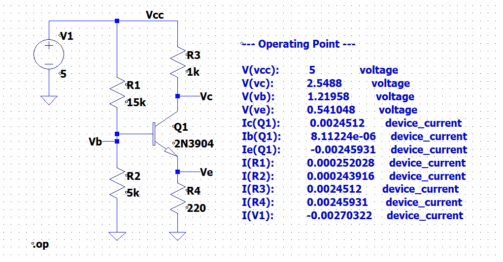
Also, you know that \$5\:\text{V}\cdot\frac{R_2}{R_1+R_2}=1.25\:\text{V}\$ and since \$R_1+R_2=20\:\text{k}\Omega\$ you can plug that in, \$5\:\text{V}\cdot\frac{R_2}{20\:\text{k}\Omega}=1.25\:\text{V}\$, and find that \$R_2=5\:\text{k}\Omega\$ and therefore that \$R_1=15\:\text{k}\Omega\$.
Plugging those into a schematic:


