5
\$\begingroup\$

I am trying to find the voltage in R2 with voltage divider, this is the schematic:

schematic

simulate this circuit – Schematic created using CircuitLab

but I can't, and I don't know how to apply the voltage divider here. What I tried to do was:

First I convert the Delta R2-R3-R4 to Y (wye), because the Voltage divider should be used in a series circuit so I tried to convert the delta to series, but that just work for find the total Resistance.

schematic

simulate this circuit

I don't know which value will take the R1 and R2 in the formula: $$ V_{out} = \frac{V_{in} * R_2}{R_1 +R_2} \\ $$

so in this case $$V_{out} = V_{R_2}$$ I am using $$V_{in} = 10v$$, but I can't figure out which should be the Total resistance in this case, I mean what is the value of: $$R_1 +R_2$$

I found the Voltage of R2 doing Mesh Analysis. But I don't if is possible to find that value whit Voltage Divider.

In the case that is possible or not, when should be used Voltage divider ?

Thanks a lot for any hint.

\$\endgroup\$
3
  • 2
    \$\begingroup\$ For reference the \$V_{34}=2.5V\$ this can be obtained (as Oli hinted) purely by inspection and with almost no math. \$\endgroup\$ Commented Apr 27, 2013 at 4:41
  • 1
    \$\begingroup\$ In your top circuit with the given values R4 does nothing, hence you can remove it from the equation. The potential at [4] and [6] is the same because \$\frac{R2}{R5} = \frac{R3}{R6}\$ \$\endgroup\$
    – jippie
    Commented Apr 27, 2013 at 6:50
  • \$\begingroup\$ This is not a voltage divider question. Forget about voltage dividers. You need to know how to reduce networks of resistors and voltage sources to equivalent circuits with just one voltage source in series with a resistor: Thevenin's theorem. A voltage divider is just a special case that comes up often. \$\endgroup\$
    – Kaz
    Commented Apr 27, 2013 at 16:47

4 Answers 4

2
\$\begingroup\$

Voltage Divider Basics and Analysis

I noticed on a later comment that you were really trying to understand how this could (potentially) be done using voltage divider theory. To start, let me remind you what a voltage divider really is:

Take this resistive voltage divider from Wikipedia:
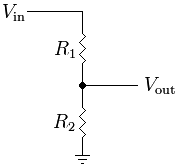
Resistive Voltage Divider

The common equation to find the output is: V_out = R2 / (R1 + R2) * V_in

But what this really boils down to is this: V_out = R2 * I_R2

Of course, in this circuit, the current through R1 and R2 is equal, so finding the value is easily done by dividing the total voltage by the total current: I = V_in / (R1 + R2)

Because R2 is located between V_out and ground, the voltage across R2 is equal to V_out. However, what would happen if a third resistor were placed in parallel to R2? Consider this modified version of the above image:
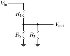
Modified Resistive Voltage Divider

The current relationship has now changed. In this circuit, I_R1 = I_R2 + I_R3. This makes the equation for the output a bit more complex: V_out = (R2 || R3) / (R1 + (R2 || R3)) * V_in

Because R2 and R3 are in parallel: (R2 || R3) = (R2 * R3) / (R2 + R3)

But the voltage across R2 is still equal to V_out. Adding another series resistor changes this:
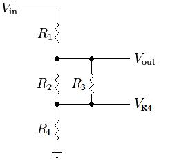
Modified Resistive Voltage Divider 2

V_out = ((R2 || R3) + R4) / (R1 + (R2 || R3) + R4) * Vin

Now, the voltage across R2 is really equal to V_out - V_R4. Adding more resistors will only further skew the relationship between V_out and V_R2. Adding a resistor in series to R3 doesn't change things too much:
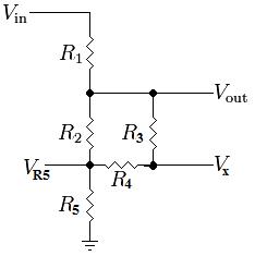
Modified Resistive Voltage Divider 3

V_out = ((R2 || (R3 + R4)) + R5) / (R1 + (R2 || (R3 + R4)) + R5) * Vin

where R2 is in parallel with the series combination of R3 and R4... This is still a big resistive voltage divider with random parallel and series resistors. The voltage across R2 is equal to V_out - V_R5.

The real complication comes with the introduction of the bottom half of the Wheatstone Bridge formed by resistors 2 through 6. Your particular circuit is very simple because all of the resistors are of equal value (the bridge is balanced), but it is a bit harder to formulate equations for a generic circuit which might have a voltage across R4:
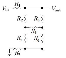
Modified Resistive Voltage Divider Circuit 4

If you really want to keep using basic resistive relationships, the next best step is to simplify the circuit. One method is to do a Delta-Wye Transform, as you mentioned in the question. However, it makes a lot more sense to do it on the the bottom half or right side of the bridge where R2 is not involved. For example, converting the bottom half of the bridge yields: Delta-Wye Transform
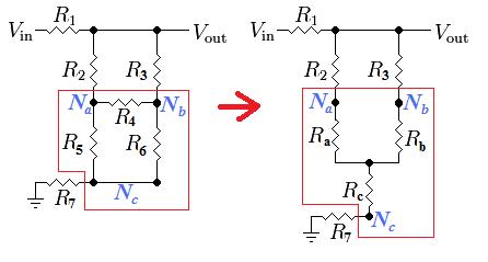
The new resistor values are found as:

  • Ra = R4 * R5 / (R4 + R5 + R6)
  • Rb = R4 * R6 / (R4 + R5 + R6)
  • Rc = R5 * R6 / (R4 + R5 + R6)

But this still doesn't solve the problem because you need to know the voltage across R2 which is now equal to V_out - V_Na. This can still be solved using voltage dividers if you use a couple of different points as outputs:
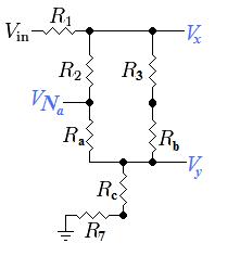
Modified Resistive Voltage Divider 5

The final solution (the voltage across R2) can finally be found using a combination of various voltage dividers and the following equations:

  • Vx = [((R2 + Ra) || (R3 + Rb)) +Rc +R7] / [R1 + ((R2 + Ra) || (R3 + Rb)) +Rc +R7] * V_in
  • Vy = (Rc + R7) / [R1 + ((R2 + Ra) || (R3 + Rb)) + Rc + R7] * V_in
  • I_R2 = (Vx - Vy) / (R2 + Ra)
  • V_R2 = R2 * I_R2

Since you said you already found the answer using Mesh Analysis, I will go ahead and put the values you should get from the above equations:

  • Vx = 10V
  • V7 = 6 & 2/3 V = 6.666...V
  • I_R2 = 0.025A
  • V_R2 = 2.5V

So it is possible to solve the circuit using nothing but voltage dividers, but we needed help from a resistor transformation. All of the basic circuit analysis techniques are based on Ohm's law: V = I*R, some of them just make more sense to use at times than others do.

Using Nodal Analysis

Considering all of your resistors are the same value, there are a few tricks to easily reduce the entire circuit down, but since that is pretty unrealistic in real life, I think it would be better to teach you a real analysis tool. There are many ways to analyse a circuit, but one of the easiest and best for many types of problems is Nodal Analysis. It is very easy to learn.

1) According to Kirchhoff's current law (KCL), the current going into any one node (point in the circuit) must be equal to the current coming out of any one node. So divide the circuit up into individual currents flowing from one node to another. The direction of the current flow is entirely up to you, it will just affect the polarity of the resulting current:
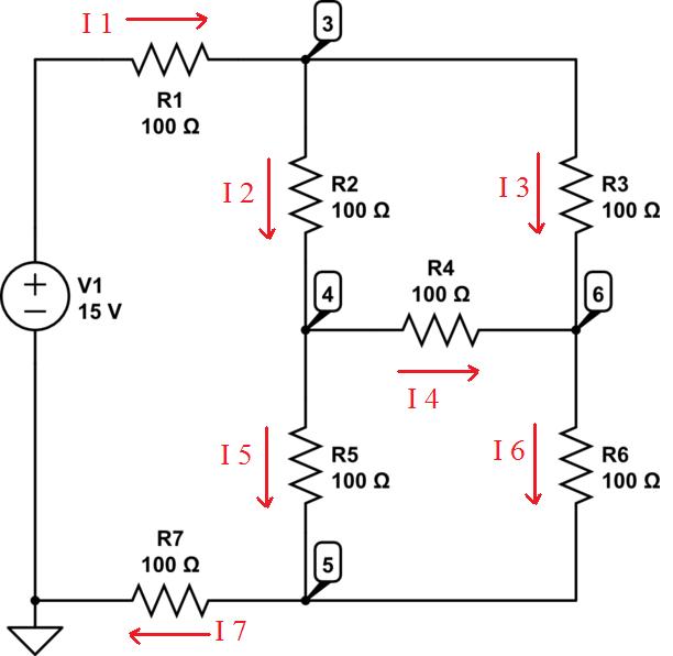
KCL

2) Form relationships between the currents:

  • I1 = I2 + I3
  • I2 = I4 + I5
  • I6 = I3 + I4
  • I7 = I5 + I6
  • I7 = I1

3) Express the currents as voltages/resistances

  • I1 = (15V - V3) / R1
  • I2 = (V3 - V4) / R2
  • I3 = (V3 - V6) / R3
  • I4 = (V4 - V6) / R4
  • I5 = (V4 - V5) / R5
  • I6 = (V6 - V5) / R6
  • I7 = (V5 - 0V) / R7

4) Using Algebra, combine and reduce the equations to find the values of the unknown voltages. To answer your specific question, the voltage across R2 would be V3 - V6 which is equal to R2 * I2.

\$\endgroup\$
2
  • \$\begingroup\$ What is the reason that current direction I4 is shown left to right ? I think I've read about the clock-wise rule, but for resistors in R4 position, I always get confused. \$\endgroup\$
    – bdutta74
    Commented Apr 27, 2013 at 5:23
  • \$\begingroup\$ The direction of the current is up to you. But, if I4 were drawn in the opposite direction, the V/R relationship would change from (V4-V6)/R4 to (V6-V4)/R4. Also, the relationships between the currents would be different. For example, instead of I6=I3+I4 it would be I3=I4+I6, and instead of I2=I4+I5 it would be I5=I2+I4. Do you see what is happening? The currents can be drawn in any direction you want, but the relationships between the currents must reflect the directions you choose. These are not currents through a loop as in mesh analysis, but currents through individual components. \$\endgroup\$ Commented Apr 27, 2013 at 6:36
3
\$\begingroup\$

I'll just give a hint here - think about the voltage across R4, and how much current will flow through it. If you need to, remove R4 and work out the voltages at points 4 and 6.

If it wasn't quite as convenient (e.g. all resistor were not the same value), you can calculate the Vth and Rth (Thevenin) for R2, R5 and R3, R6 (i.e. points 4 and 6). Then work things out from there.

\$\endgroup\$
1
  • \$\begingroup\$ Hello, Thanks a lot for the answer, I have to said that takes me a good 1 hour and a half to get the hint, but finally a understand. So the current across R4 is I = 0, and V = IR . But, there is always a but, I want to know how to use here Voltage Divider, I think that should be possible to use voltage divider because is just the Ohm's Law and should works everywhere, but I don't know how to apply Voltage Divider here, I will continue trying to find the way. Anyway your help was very, very handy because teach me that I have to understand the circuit before to jump in the math \$\endgroup\$
    – Cesar
    Commented Apr 27, 2013 at 15:20
1
\$\begingroup\$

I think the best approach is the one Clothier mentioned above. But you should read more on wheatstone bridge since your values are the same. Why-Delta conversion requires more processes and generally those are tedious. If those processes are still tedious, if i were you i will use meshes, and you got the following equations:

$$15 = I_{1}(400)-I_{2}(100)-I_{3}(100)$$ $$0 = -I_{1}(100)+I_{2}(300)-I_{3}(100)$$ $$0 = -I_{1}(100)-I_{2}(100)+I_{3}(300)$$

Or use KCL, and then:

$$v_{3}+v_{3}-v_{4}+v_{3}-v_{6}=15$$ $$v_{4}-v_{3}+v_{4}-v_{6}+v_{4}-v_{5}=0$$ $$3v_{6}-v_{3}-v_{4}-v_{5}=0$$ $$3v_{5}-v_{4}-v_{6}=0$$

Good luck on that, in the future you will learn better methods such as Thevenin, and CAD simulations.


\$\endgroup\$
1
  • 1
    \$\begingroup\$ Yes, thanks a lot for the help, but as I said in the post I already find the answer, the approach of the question is to find that VR2 with Voltage Divider , why? because I think that should be possible, and frankly I think that should be so simple but I can't figure out how. Basically I don't know what should be the total resistance value in the Voltage Divider formula for find VR2. Yes, Thevenin is in the next chapter but I want to really understand the foundations before I move to the next concept and Voltage Divider is one of the basics. Thanks a lot for the help. \$\endgroup\$
    – Cesar
    Commented Apr 27, 2013 at 15:09
1
\$\begingroup\$

In this circuit situation with all R-values equal, the evaluation is quite simple. First note that V at 4 & 6 must be equal hence R4 has no current and may be disregarded. The network R2-6 is basically another 100 ohm equivalent resistance. That makes the voltages at 3 & 5 2/3 and 1/3 of the V-input, i.e. 10 & 5 V respectively. Due again to the resistor value equality, V across R2 must be 1/2 of the 5v between 3 & 5, or 2.5 volts. Q.E.D.

\$\endgroup\$

Your Answer

By clicking “Post Your Answer”, you agree to our terms of service and acknowledge you have read our privacy policy.

Not the answer you're looking for? Browse other questions tagged or ask your own question.