Take this SR05 for example. The data sheet explains that you can use it with or without a reference voltage at pin 4. So why have the steering diodes at all for ESD protection? Is it to ensure that the TVS only receives bias when the voltage at pin 2 and 3 are greater than or equal to the breakdown voltage of the TVS?
3 Answers
First, establish what the function is.
Suppose we have digital logic signals, subject to ESD strike.
It is typically required to constrain these signals to the GND...VCC range, or as close as is reasonably possible.
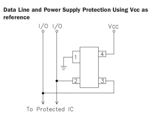
Since we have VCC supply handy, we can use a simple pair of diodes (per signal) for this purpose. One up from GND to signal, one from signal to VCC.
That's it, that's the trick, that's all there is to it!
What if we don't have VCC handy? What if VCC isn't strong enough to handle an ESD pulse (or other surge)?
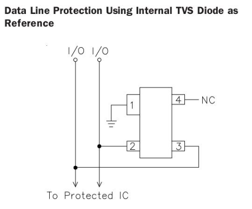
Okay, alright, fine, then... let's put in a zener diode (a large enough one, rated for duty: a TVS) to clamp excessive voltage. Now we don't even need VCC to handle ESD (or other surge) currents. Indeed we can handle those currents locally (say, at the connector where the ESD current was introduced).
So why not TVS the signal directly?
A unidirectional TVS (single zener) already has the reverse clamping diode, and its breakdown voltage affords the positive clamping (no VCC needed at all). That seems adequate, right?
In fact, sometimes we do. Often, multi-TVS array chips are used, when signals have lower bandwidth. General purpose I/O, RS-422/485, CANbus (see PESD1CAN, it's even in the name!), etc. are typical applications.
The TVS has about 100pF of capacitance*, which is acceptable for low impedance, or slowly varying signals. It is wholly unacceptable for fast signals, like high-speed USB, HDMI, Ethernet, etc. In those cases, we must separate the signal from the TVS, using a PN diode having much lower capacitance.
*For typical logic-level parts rated for 15kV+ ESD. This is a ballpark figure of course, and varies between all sorts. You can reasonably assume, however, if something claims much lower capacitance (like under 10pF): it's almost certainly a series-diode type. (The main exception I know of, are polymer type limiters; which boast extremely low capacitances, but also have much higher peak clamping voltages.)
The series diode has the downside of adding more resistance to the circuit, increasing the peak clamping voltage; it may also be so small that it gets damaged progressively by the intense ESD pulses (currents of 10A+, on signals that are otherwise a few mA; it's a big deal for micron-sized semiconductors!). ESD typically doesn't occur very often, so this can be an acceptable compromise on equipment.
Another point about VCC clamp vs. TVS diode: often, the parts we are protecting have their own clamp diodes to VCC/GND. If VCC is disabled (say, the device is powered off / in storage), current will flow into the device's VCC clamp diodes first (because VCC is at GND), meanwhile the TVS won't start conducting until 5V or whatever. It's better to use (VCC biased) clamp diodes for this situation, in which case any internal (VCC to GND) TVS is either bonus value (ensures clamping against overvoltage), or just free along for the ride and doesn't matter (these components hardly cost more [than a pure-diode clamp array], you're basically getting the TVS for free).
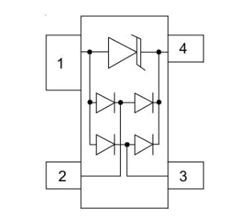
Also, the apparent "full wave bridge" arrangement of the two-line array (as pictured), can be used directly as a bidirectional clamp as well; ±Vclamp is one TVS plus two diode drops. This may be handy when clamping differential voltages (e.g. Ethernet on the media side).
Mostly we're concerned with logic or signal inputs (and outputs), so these (GND and VCC connected) TVS arrays are very popular.
-
\$\begingroup\$ @What applications would it be acceptable to use only a TVS? Could you use a TVS to protect a power MOSFET pin that supplies DC for example? \$\endgroup\$– BobaJFETCommented Aug 25, 2023 at 21:22
-
1\$\begingroup\$ @BobaJFET "acceptable for low impedance, or slowly varying signals". MOSFET load switches are typically both, and TVS are often found here. \$\endgroup\$ Commented Aug 25, 2023 at 22:06
Why use a steering diode with a TVS for ESD protection?
The steering diodes form a bridge rectifier with the TVS on the rectified output hence, this makes the TVS bi-directional (if you want to use it that way).
-
\$\begingroup\$ Picture? Trying to understand what rectified output you're talking about and how it's bi-directional. \$\endgroup\$– BobaJFETCommented Aug 24, 2023 at 20:50
-
1\$\begingroup\$ Look at the 1st picture in your question = bridge rectifier feeding a TVS @BobaJFET \$\endgroup\$– Andy akaCommented Aug 24, 2023 at 21:24
So why have the steering diodes at all for ESD protection?
Those aren't necessarily steering diodes although that's a fine way to call them I think. They are definitely switches that turn on when the GND and REF voltages are exceeded. These switching diodes take less space on the die than the TVS, and they allow using a fixed reference voltage or the TVS voltage as the upper limit. Very convenient.
If you didn't have the switching diodes, you'd need something else to act as a switch. And you'd be stuck using TVS elements for that. That's not very flexible. And diodes are cheaper than TVSes in terms of die area and have better yield. So diodes are preferable as witches.
The data sheet explains that you can use it with or without a reference voltage at pin 4.
The "reference" connection is an additional energy sink. The important bit is not shown on the picture: the distributed power plane-to-ground plane capacitance.
The reference voltage connection allows for a tighter clamping range than the TVS tolerance provides.


