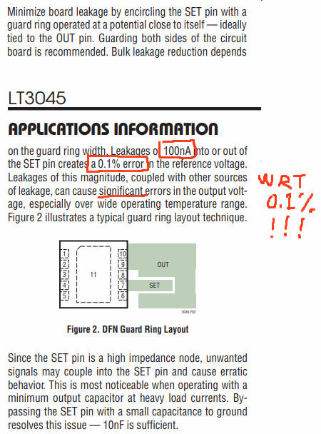
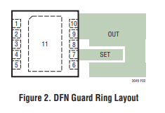
From the datasheet:

100nA might be typical leakage of a contaminated PCB, say with mildly conductive flux residue, on a humid day.
0.1% accuracy is extremely precise as regulators go; with 1% initial accuracy, it will have to be trimmed to achieve finer precision, but presumably will be reliable (stable) thereafter.
Since from your comments, you have no critical performance requirements, then this consideration is not important and can be ignored.
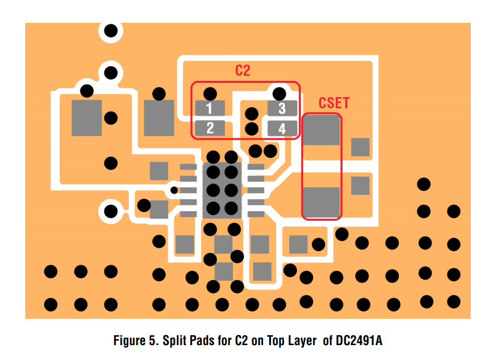
As for why they didn't in the eval board, probably because it's an example, not a specific application. They also have control over the assembly, e.g. can specify suitable flux type, and washing to clean it. Whether the board remains as clean after its end users (design engineers) have made modifications, is entirely up to them [the users].
They may also simply only care about demonstrating the low noise performance, the absolute DC voltage of which doesn't matter.
Or they may simply not care. Eval boards and appnotes are notoriously dubious in quality; they are, at best, starting points for further development. As the name suggests, "eval board" is for evaluation purposes; it's not a finished product, and need not demonstrate any particular features of the devices used. (Presumably it'll be made to cover some, most even, but almost certainly not all, features.)
As a beginner, even if cost is no object, going for "maximum performance" is generally ill advised, especially when you have no apparent way to show benefit from whatever nebulous variables are being "performed".
Now, in this particular case, from a quick scan I don't see any obvious pain points, but generally speaking, performance comes with a cost.
Let me illustrate through automotive example: consider all those video clips of idiotsdrivers wiping out and crashing their, you know, Corvette, Mustang, Porche, whatever. Maybe they're new drivers, not used to how the vehicle handles; maybe they're in fact experienced drivers and just made a mistake. Whatever the case: sure they're performance cars, but that performance comes at a cost. Hit the throttle too hard, take a corner too tight, you lose traction and it's all over, at the very least clipping a curb damaging wheels/suspension, at worst killing innocent bystanders. There is very good reason why consumer cars are boring to drive: they're also safe to drive. Or more precisely: they're easy to drive safely, and hard to drive unsafely.
So it is with electronics. Choose common, widespread, well understood parts, with the least likelihood of unexpected behavior. An LM7805 (or 317 or etc.) might well do you better (assuming other constraints are satisfied), as it's far less critical of errors in layout or component choice, basically can't be miswired in a nondestructive way (you can only get "so" wrong, with only three pins), and is extraordinarily well documented. They're also easier to solder, not having an invisible middle pad that requires a reflow process.


