0
\$\begingroup\$

I am designing an FPGA-based SOM. There are I2C slave and master devices on the board. The I2C bus on the board includes an MCU that acts as a system manager and a bridge from UART to I2C, a PMIC device configured by I2C, a component containing an RTC and temperature sensor, the FPGA itself, the clock generator, and the output to the external environment from the mezzanine connector outside the board.

The FPGA has a power-up sequence. FPGA IOs are not supposed to rise before the VCCIO voltage, so I have to go to isolation on the bus. For this reason, I decided to make a simple MOSFET-based level shifter so that it would take up little space and be cheap.

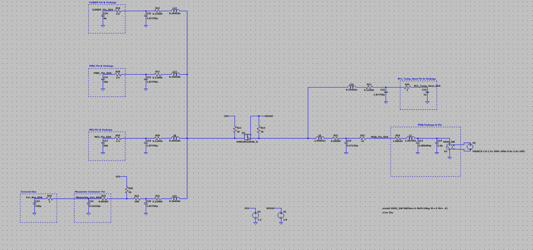
I made a SPICE simulation for a component containing two N-channel MOSFETs in a single package. The line was designed to meet the fast-mode I2C standard. Already the RTC/temperature sensor component and FPGA are using 1.8 V; other devices are using 3.3 V.

In theory, I should be able to provide both isolation and level shifting, because if 1.8 V VCCIO is not available, the MOSFETs will be cut off and there will be no leakage from the 3.3 V I2C line to the FPGA pin (a leak that may cause problems).

However, in the simulation I made with the SPICE model offered by the manufacturer of the MOSFET, while there is no problem during normal operation when VCCIO is removed and there is no switching on the 3.3 V side, 3.1-odd V leakage appears on the FPGA side. Additionally, if there is switching on the 3.3 V side when there is no VCCIO, I still read 1.8 V on the FPGA side.

What exactly do you think is the reason for this? Am I missing something? What are your possible solution suggestions?

Note: All parasitics on the bus were made taking into account the FPGA's IBIS model, component datasheets, and possible path widths and lengths in the PCB stack.

Normal operation is the same for SCL and SDA: Normal operation is the same for SCL and SDA
Normal operation, VCCIO side waveform: Normal operation, VCCIO side waveform

Normal operation, 3.3 V side waveform: Normal operation, 3.3 V side waveform

With no VCCIO (floating) and no switching: With no VCCIO (floating) and no switching
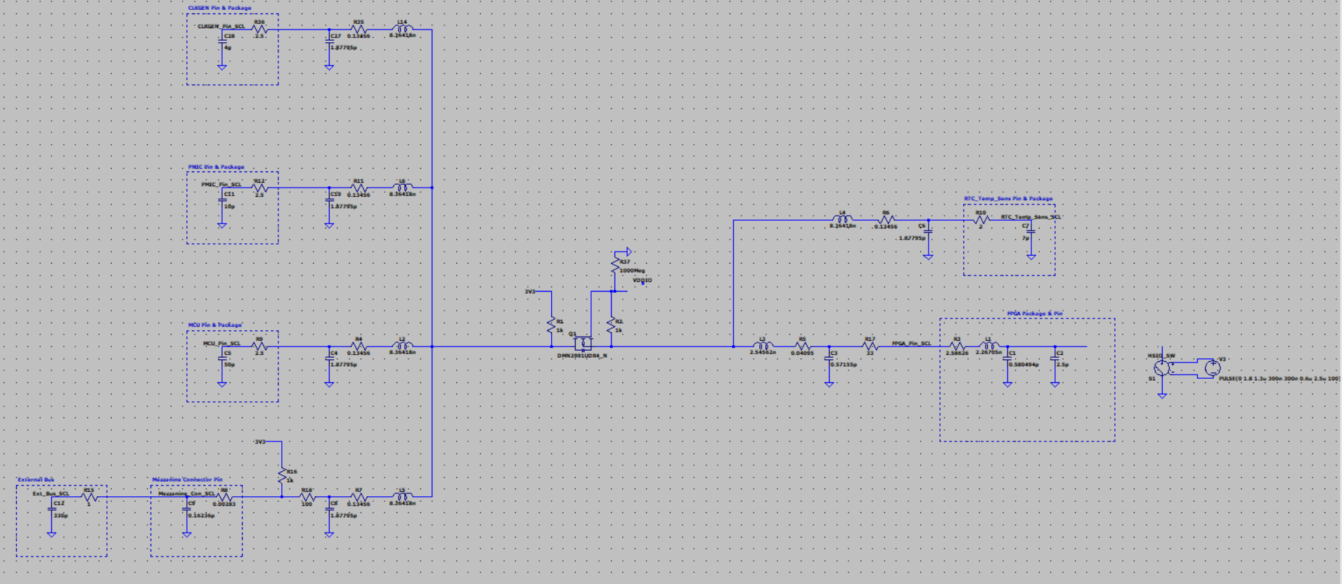
VCCIO side waveform with no VCCIO (floating) and no switching (3.3 V side already showing flat 3.3 V): VCCIO side waveform with no VCCIO (floating) and no switching (3.3 V side already showing flat 3.3 V)

Transistor drain current waveform with no VCCIO (floating) and no switching on the 3.3 V side: Transistor drain current waveform with no VCCIO (floating) and no switching on the 3.3 V side

When there is no VCCIO (floating) and there is switching on the 3.3 V side: When there is no VCCIO (floating) and there is switching on the 3.3 V side
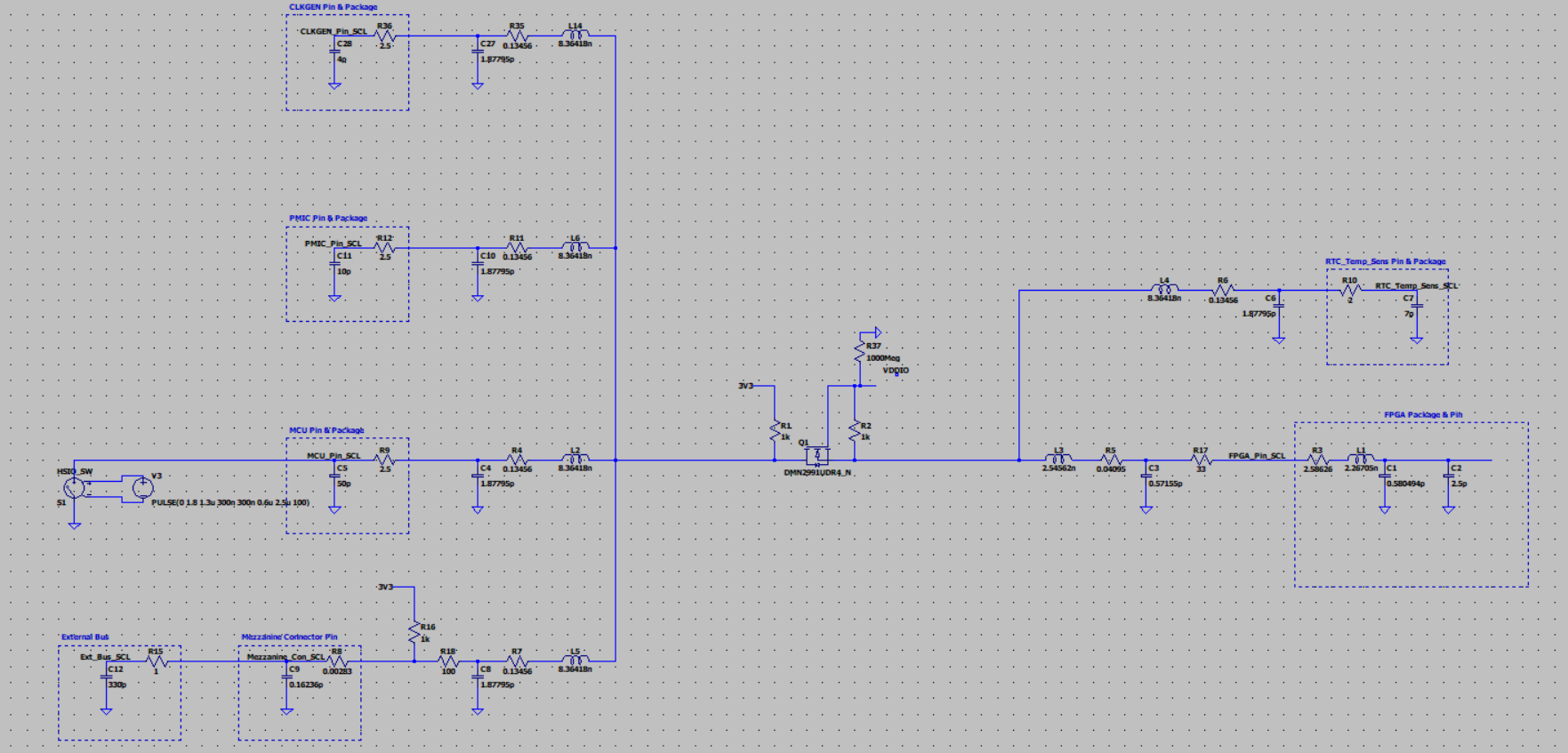
VCCIO side waveform with no VCCIO (floating) and 3.3 V side switching (3.3 V side same as normal operation): VCCIO side waveform with no VCCIO (floating) and 3.3 V side switching (3.3 V side same as normal operation)

\$\endgroup\$
7
  • \$\begingroup\$ There are dedicated ICs for these applications. Cheap, simple, realiable. See DigiKey/Mouser ... etc \$\endgroup\$ Commented Jan 24 at 18:29
  • \$\begingroup\$ Yes, I know. However, this solution is more logical for size, cost, and external component usage cases. I have already investigated dedicated level shifters and then made decisions this way. \$\endgroup\$
    – electroeso
    Commented Jan 24 at 22:10
  • \$\begingroup\$ Check Fairchilds FXMAR2102 - 1.2x1.4mm, 0.16€/pc @5kPcs, Output-Enable (Can be Handy) and no passives (If layout is done correct) required. Will neither be cheaper, nor simpler, nor more reliable with a discrete solution. Also think about your engineering time. \$\endgroup\$ Commented Jan 25 at 0:50
  • \$\begingroup\$ Oh come on, how did I miss this? I did a lot of research beforehand, I remember seeing something similar. But it made sense to try the discrete solution to push the 400p capacitance limit and for cheap isolation (discrete resistors were needed anyway, I didn't want to add an enable resistor and VCC line capacitors). However, this device seems to give exactly the effect I want in terms of isolation. Engineering time is always important, but maybe it was a little wasted this time, okay :)) Thank you very much for the suggestion. I will try this. \$\endgroup\$
    – electroeso
    Commented Jan 25 at 1:59
  • \$\begingroup\$ @electroeso Just be careful with that FXMAR2102 chip. They look good on paper and people put them on their design. Similar bi-dir auto-directional buffers are made by TI as well, and most questions here about them is why they don't work as expected, but the expectations are genrally unrealistic and the chip is used in an environment it cannot work properly. There are less smart I2C level shifting solutions that may work better because they are simpler. \$\endgroup\$
    – Justme
    Commented Jan 25 at 9:31

1 Answer 1

1
\$\begingroup\$

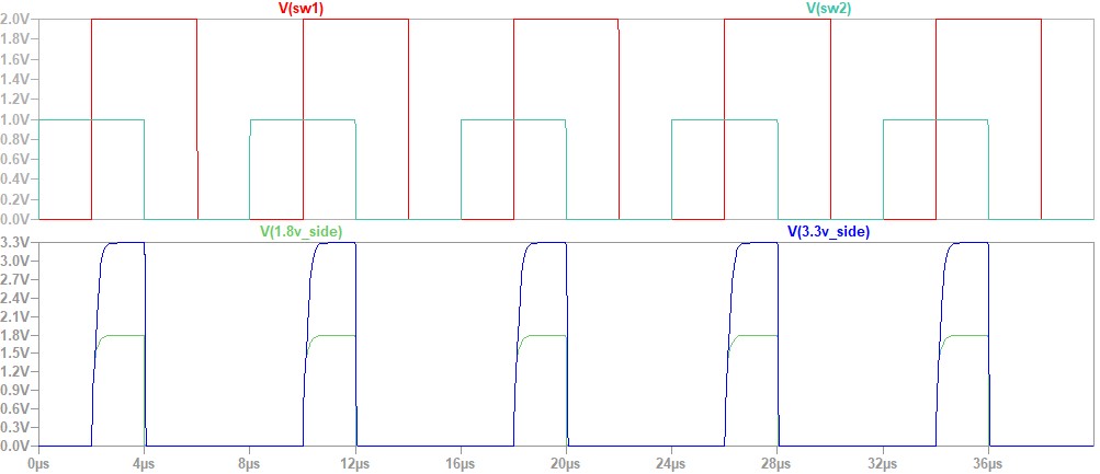
I am not sure why your last waveform looks like that. I am able to simulate correctly. Here is my simpler test circuit. enter image description here

The DMN2991UDR4 NMOS Spice model was downloaded from here and was renamed to DMN2991UDR4.mod and included in the circuit using the .inc directive. And here is the waveform. enter image description here

S1 S2 Outputs
ON OFF Both 0V
OFF OFF Both raise to 3.3V and 1.8V, respectively
OFF ON Both 0V
ON ON Both 0V

Note: V(sw1) (red) is set to 2V instead of 1V like V(sw2) (cyan) just to make the waveforms clearer when plotted together. V(sw1) = 2V switches S1 OFF and V(sw2) = 1V switches S2 OFF.

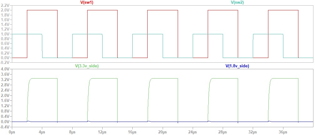
Now, if the gate and the 1.8V side are pulled down to 0V like below enter image description here

The waveforms become enter image description here

The 1.8V side remains low (blue waveform) regardless of whatever signal that appears on the 3.3V side, which means the 1.8V side is isolated from 3.3V side like what you have expected.

Edited

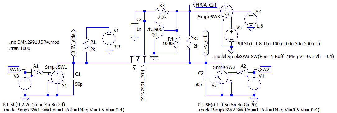
If you need to wait till the FPGA to complete its power-up sequence and you are able to spare an I/O pin, then here is a solution using one PNP, one capacitor, and 2 resistors enter image description here

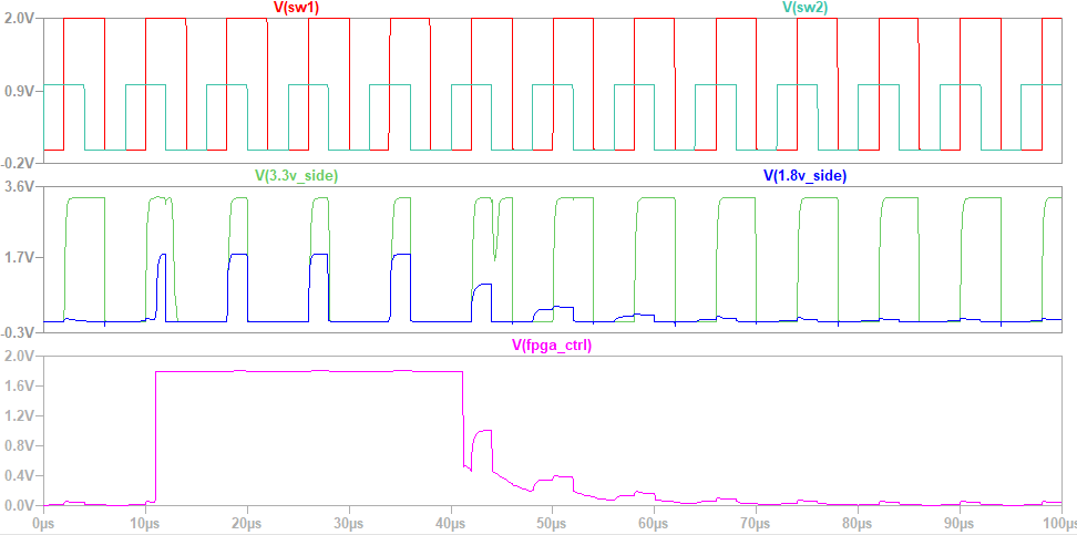
And here is the waveforms enter image description here

The FPGA turns ON (FPGA_Ctrl=1.8V) the voltage shifter when it is ready and then it is powered down (FPGA_Ctrl=HiZ) as shown in the purple waveform. It takes a while for the C3 to discharge, but eventually the 1.8V side is isolated. The signal bumps you see when it is completely isolated are less than 90mV in the simulation.

\$\endgroup\$
5
  • \$\begingroup\$ Huge thank you for your answer. Unfortunately, you're missing a point. 1.8V side will be floating for a bit of time up to when the FPGA power-up sequence is done. Not grounding. Meanwhile, MCU will configure PMIC, so this means 3.3V is active before FPGA's 1.8V VCCIO rail, and isolating any voltage from FPGA IOs is critical. Because of simulating this scenario, I put a huge resistor on the 1.8V side. Because LTspice is ridiculous if you actually leave any node floating. \$\endgroup\$
    – electroeso
    Commented Jan 24 at 22:32
  • \$\begingroup\$ If you can spare an I/O pin then you can use my new circuit. I have updated my answer. \$\endgroup\$
    – kaosad
    Commented Jan 25 at 7:30
  • \$\begingroup\$ I edited again because I forgot that the FPGA_Ctrl pin must float when powered down. \$\endgroup\$
    – kaosad
    Commented Jan 25 at 7:58
  • \$\begingroup\$ Thank you so much. This PNP solution is very logical but not simple from my perspective (size and area are big issues for this design). I may use it if can't find a better solution. \$\endgroup\$
    – electroeso
    Commented Jan 25 at 10:16
  • \$\begingroup\$ Actually you can omit the PNP. You just need 1 capacitor and 2 resistors. The turn OFF period of the voltage shifter would be around 25usec (from my simulation). You can use 0201 (0.6mm * 0.3mm) capacitors and resistors if you are concern with the area occupied. You can pack them nicely and that would be roughly the size of the DMN2991UDR4. Also note that you need only one set to control all the voltage level shifters. \$\endgroup\$
    – kaosad
    Commented Jan 25 at 11:12

Your Answer

By clicking “Post Your Answer”, you agree to our terms of service and acknowledge you have read our privacy policy.

Not the answer you're looking for? Browse other questions tagged or ask your own question.