7
\$\begingroup\$

I'm trying to train up on isolated power converters and magnetics.

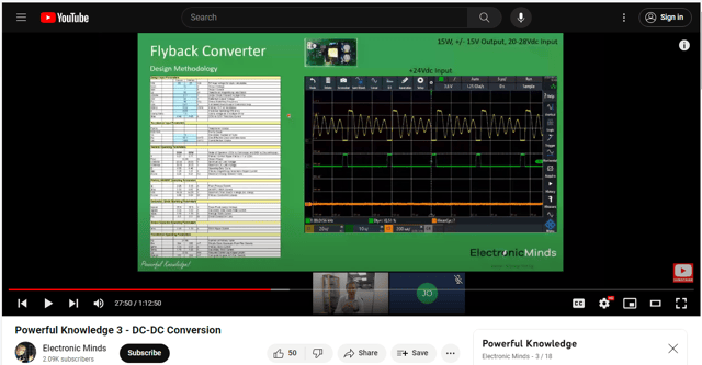
I am going through a webinar series created by Electronic Minds out of the UK called Powerful Knowledge. It's on YouTube if you'd like to see it for yourself. In episode 3 titled "DC-DC Conversion" at 29 minutes he shows the Vds, Vgs, and load current waveforms for a flyback design (link to that YouTube video here and screenshot below).

screenshot of waveforms

(click image for larger version)

As he raises the load current up from zero, it's in DCM and the duty cycle raises as expected. After a point though, it crosses over into CCM, and the duty cycle doesn't change even with him still raising the load current.

What is the controller doing to maintain the output voltage if the duty cycle is constant like that?

\$\endgroup\$
1
  • 5
    \$\begingroup\$ I recommend you have a look at my seminar on switching converters but also my APEC 2011 presentation on the flyback converter. Closing the loop even in CCM where the duty ratio seems constant, brings other benefits like better line regulation (when the input changes), lower output impedance and overall stability versus temperature drift to cite a few of the benefits brought by feedback. \$\endgroup\$ Commented Apr 24 at 17:08

3 Answers 3

5
\$\begingroup\$

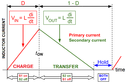
It's impossible to increase the CCM duty cycle on a fixed load without the output voltage changing. Consider the DCM flyback case: -
enter image description here

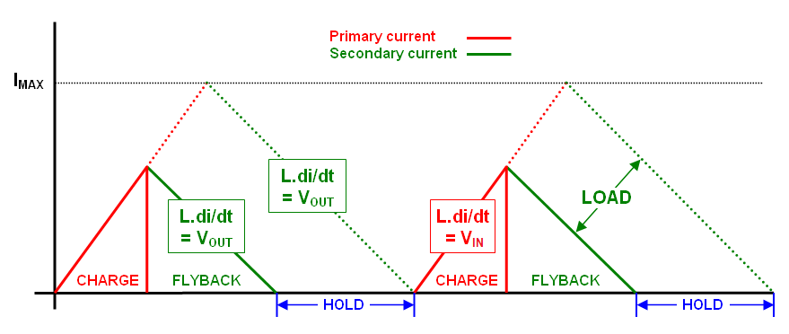
The slopes of the rise and fall of transformer current are wholly dictated by \$V_{IN}\$ and \$V_{OUT}\$ for an inductor of a fixed value. And, because there is a period at the end of the transfer phase in DCM, duty cycle variations are permissible: -
enter image description here

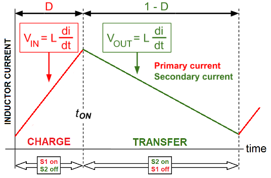
But, CCM has nowhere to accommodate a change in duty cycle: -
enter image description here

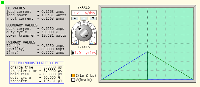
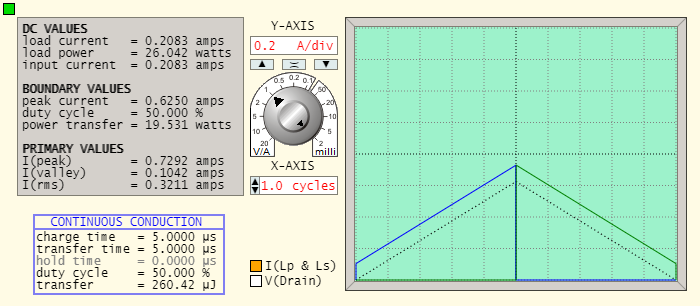
The images above come from my basic website and are for a flyback converter with a 1:1 transformer. I also have a waveform generator that you can use for testing the change from DCM into CCM as the load current increases. This is an example for a 1:1 transformer where the output voltage equals the input voltage (125 volts). DCM Operation is at 100 kHz with a 1000 Ω load: -
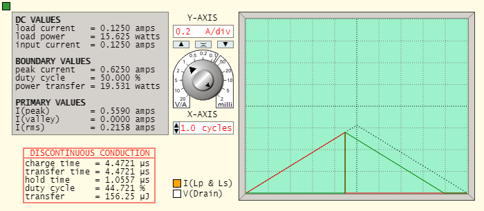
enter image description here

If I decrease the load to 800 Ω, operation is on the boundary between DCM/CCM: -
enter image description here

If I lower the load to 600 Ω, operation is clearly in CCM: -
enter image description here

The duty cycle cannot change because there is nowhere to accommodate that change hence, the whole primary and secondary waveform rises.

How do flyback converters operating in CCM regulate their output?

It naturally regulates in CCM due to the way the slopes of primary and secondary currents link together.

What is the controller doing to maintain the output voltage if the duty cycle is constant like that?

The controller doesn't need to do anything, it naturally happens once CCM is entered.

If the charging phase of the switching cycle begins when there is still magnetic energy in the transformer core (left over from the transfer phase) then, the charging current has to commence at a positive value and not a zero amp value (as in the case of DCM). That cannot be avoided in CCM.


Simple example of a flyback converter with fixed duty and switching frequency

The image shows a flyback converter's current waveforms from the instant power is applied. Although the duty cycle and switching frequency are fixed, CCM is naturally entered in the first few cycles but, after the output voltage rises towards a settled value, DCM takes over: -

enter image description here

  • The red part of the waveform is charging current and,
  • The green part of the waveform is the transfer current to the load
  • Red remains fixed in duration and angle
  • Green starts shallow and gradually becomes steeper
\$\endgroup\$
4
  • \$\begingroup\$ Is there any way you could explain further what you mean by "It naturally regulates in CCM due to the way the slopes of primary and secondary currents link together." How does the DC component of the core flux density just increase if the duty cycle didn't change to get it there? \$\endgroup\$ Commented Apr 24 at 17:35
  • 1
    \$\begingroup\$ I added a paragraph at the end as you left your comment @MichaelBeckwith \$\endgroup\$
    – Andy aka
    Commented Apr 24 at 17:36
  • \$\begingroup\$ Thanks @Andyaka. I think my confusion lies in not understanding how at the end of the cycle, as load increases, there is more energy left in the core than at lower load. I do understand that in CCM, the core never demagnetizes, so the primary current starts at a non-zero value at the beginning of the charge period. How does that dc component of the core energy get built up in the first place to support the higher load current? \$\endgroup\$ Commented Apr 24 at 17:58
  • 1
    \$\begingroup\$ If the output voltage droops under load, the rate of change of current in the transfer phase must be shallower therefore, there has to be magnetic energy left in the transformer core when the switching cycle restarts. This means that the charge current must commence at a higher level. \$\endgroup\$
    – Andy aka
    Commented Apr 24 at 18:40
8
\$\begingroup\$

Once in CCM, the duty cycle doesn't need to change to react to a change in load current, so the controller does not need to do anything. Moreover, the controller must not do anything, as any change in duty cycle would have a proportionate effect on the output voltage.

How then is the load current change being "regulated"?

When the load current rises to a level that is above the average output inductor current, the output voltage will sag a little bit as the output capacitor will be gradually discharged. As a result, the downgoing slope of the current (see graphs from Andy) will be less steep. Therefore, at the end of the period, current (and remaining core flux) will end at a slightly higher level than it started at.

This increase of the inductor current will stop once the average inductor current has again stabilized at the load current. This equilibration happens even without a change in duty cycle, but it can be accelerated if the controller slightly increases the duty cycle momentarily.

\$\endgroup\$
1
  • 1
    \$\begingroup\$ Thank you! If I could give both your and Andy's replies a green check I would. I marked Andy's as he got me 90% of the way there, but your explanation got me across the finish line \$\endgroup\$ Commented Apr 24 at 18:11
0
\$\begingroup\$

In the absence of electrical resistance, the time-average voltage across an inductor must be essentially zero (it may be non-zero for short amounts of time, but the longer the timespan being considered, the smaller the average voltage must be within that timespan), and DC/DC converters could be operated all the time in continuous mode. The reason switching power supplies are often operated in discontinuous mode when load currents are very small is that when operating in continuous mode, the inductor would spend almost half of its time either taking excess energy back from the load or pushing excess energy back into the supply. The purpose of discontinuous mode is to disconnect the inductor from the supply before it receives much excess energy, thus reducing the amount of excess energy that will need to be pushed into the load, and drawn from the load, and pushed into the supply. The amount of energy that would be in excess of what the load is going to need will be very sensitive to load current, thus necessitating a tight feedback loop in discontinuous mode. In continuous mode, however, in the absence of resistance, the voltage ratios between "take energy from supply" and "feed energy to load" states would need to equal the inverse ratio of the times spent in those states, regardless of load current. In practice, resistance of inductors and switching elements causes the voltage ratio not to match the duty cycle, but feedback mechanisms won't need to be nearly as sensitive as to regulate voltage in a discontinuous-mode switcher.

\$\endgroup\$

Your Answer

By clicking “Post Your Answer”, you agree to our terms of service and acknowledge you have read our privacy policy.

Not the answer you're looking for? Browse other questions tagged or ask your own question.