2
\$\begingroup\$

Can anyone tell me what the yellow components on this PCB are please?

At first I thought diode - they measure 0.7 V but then 1.7V when measuring reverse-bias.

Then I thought capacitor - but the both measure 0 nF.

What test should I do to find out what they are?

They are part of a HALJIA Digital light intensity sensor module. The circuit is design to switch a digital output when the light reaches a certain level that is adjustable using the potentiometer.

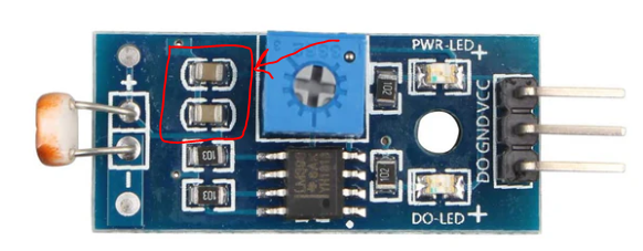
enter image description here

\$\endgroup\$
1
  • 1
    \$\begingroup\$ What test should I do to find out what they are? ... remove from board and measure \$\endgroup\$
    – jsotola
    Commented May 5 at 22:14

2 Answers 2

10
\$\begingroup\$

Completely bog-standard SMD MLCC ceramic capacitors. You can probably not measure them accurately in the circuit. If you measure them, I expect something in the range of 0.1 to 10 µF.

\$\endgroup\$
9
\$\begingroup\$

They are most likely 100nF ceramic capacitors with something like 10V or 16V rating.

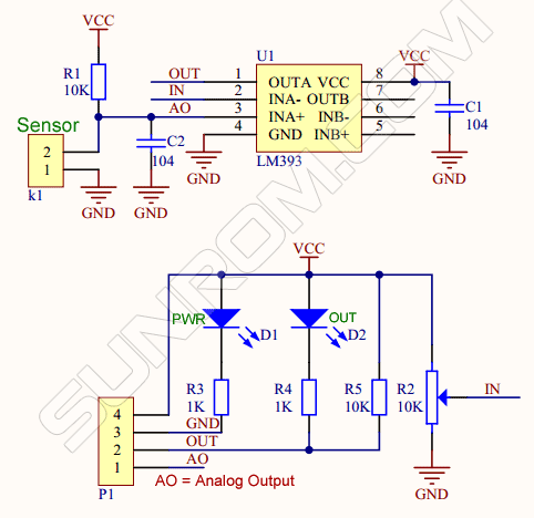
From here is a schematic for a unit that appears identical:

enter image description here

The caps would be C1 and C2.

This kind of capacitor is not usually marked, but we can confirm the resistor values and the IC part number are the same as in the above schematic.

\$\endgroup\$

Your Answer

By clicking “Post Your Answer”, you agree to our terms of service and acknowledge you have read our privacy policy.

Not the answer you're looking for? Browse other questions tagged or ask your own question.