0
\$\begingroup\$

In the sample schematic Microchip Technology supplies in the data sheet for their MCP39F521 shown below, it appears that V1- is grounded. (V1- and V1+ are input pins for determining voltage.)

  1. Does this mean that if I am trying to analyze US 240 VAC (with two live and no neutral), this circuit would only show 120 VAC?
  2. If the above is true, can I simply replace the V1- in the example with a clone of the V1+ voltage divider (connected to the opposite line of course) to achieve the actual voltage?
  3. If that is correct, would the values for the voltage divider components remain the same? Each line (L1, L2) still maxes out at 120 VAC by itself, but I'm not sure if this IC references them against each other, or against ground.

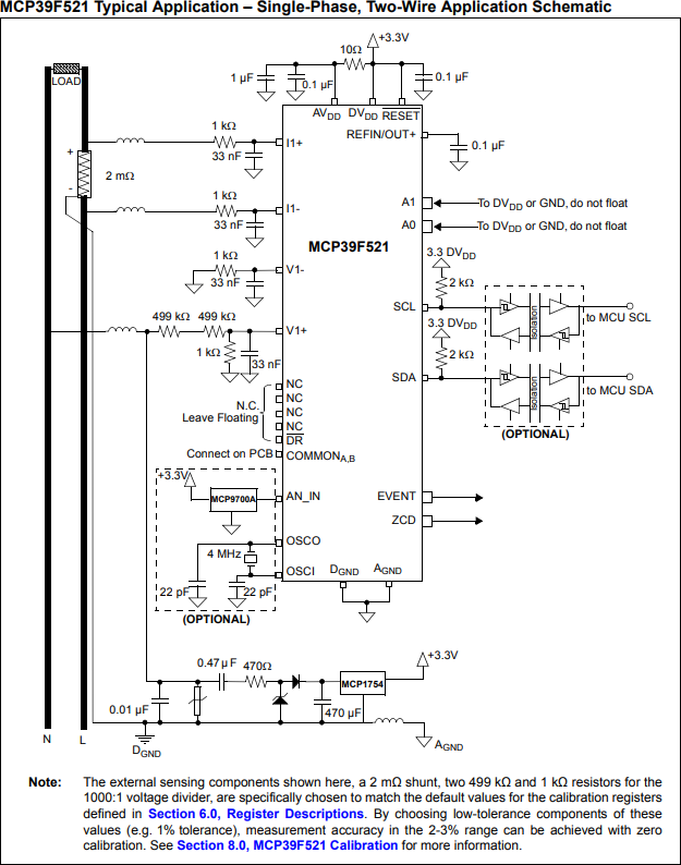
MCP39F521 Typical Application

\$\endgroup\$
9
  • \$\begingroup\$ This circuit has no reference to mains earth. The reference point in the schematic is L. For two phase N would become L2. The voltage divider and the psu section will need component value changes for 240V. Be sure to fully understand how this circuit works - connecting mains earth will most likely cause sparks and smoke. \$\endgroup\$
    – Kartman
    Commented Jul 14 at 0:35
  • \$\begingroup\$ @kartman Isn't A_GND the reference to mains earth? From the linked data sheet: "Analog Inputs (I+,I-,V+,V-) w.r.t. AGND ...................-2V to +2V" \$\endgroup\$ Commented Jul 14 at 1:17
  • 2
    \$\begingroup\$ Such is the problem with the term ‘ground’. You can see that L is connected to the symbol Dgnd. If Agnd is mains earth(protective earth/PE) the you’ll get smoke. Mains earth plays no part in this circuit. Any reference to gnd is simply a common point. Note that this circuit is ‘live’ and requires isolation if connected to circuitry that can be touched or is referenced to mains earth. You need to fully understand the implications or working with mains otherwise is is very easy to electrocute yourself, be injured by things exploding or damaging your computer and/or property. \$\endgroup\$
    – Kartman
    Commented Jul 14 at 2:28
  • 1
    \$\begingroup\$ If your already available DC supply is related to earth/PE in any way, don't use it here. \$\endgroup\$
    – Jens
    Commented Jul 14 at 12:53
  • 1
    \$\begingroup\$ Eric - don’t assume as it may kill you. There is no magic happening in this circuit apart from that it’s 0v reference is actually Live. Which is 120VAC in your instance. As far as the chip is concerned, the concept of neutral and PE don’t exist. It simply measures the voltage between two points. In this circuit, the L wire is the point of reference as in 0V. The N wire is 120VAC. Agnd and Dgnd must be near identical in voltage otherwise the chip will die - read the datasheet. If in doubt, use a current transformer and a voltage transformer so the MCP39F521 is fully isolated from the mains. \$\endgroup\$
    – Kartman
    Commented Jul 14 at 14:33

1 Answer 1

1
\$\begingroup\$

The answers in reference to the comments are:

  1. No. If we substitute L2 for the N in the circuit, the voltage divider on V1+ would need recalculating.
  2. No. L (or L1 for two phase) is the 0V reference.
  3. No. The chip measures the voltage between V1- and V1+. In this circuit, V1- is effectively L1. The voltage from L2 is divided down to suit the input range of V1+.

A current transformer or Rogowski coil along with a ‘normal’ iron core transformer can be used to isolate the mains from the measurement circuitry. The circuit as shown does not do this and instead requires other circuitry connected to the MCP chip is floating and not connected to other devices & can not be touched or that there is suitable isolating circuitry.

\$\endgroup\$
1
  • \$\begingroup\$ Thank you for the answer. The lack of isolation with high voltages and currents was one of my primary concerns and why I posted the question in the first place, though in retrospect I didn't make that clear. I wonder why they don't use transformers in their example circuit (as they've included isolation on the other end, the I2C side)? Perhaps I am not their typical use case for this IC. \$\endgroup\$ Commented Jul 14 at 15:05

Your Answer

By clicking “Post Your Answer”, you agree to our terms of service and acknowledge you have read our privacy policy.

Not the answer you're looking for? Browse other questions tagged or ask your own question.