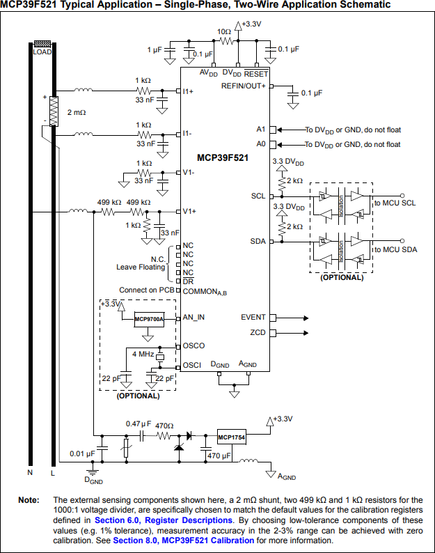
In the sample schematic Microchip Technology supplies in the data sheet for their MCP39F521 shown below, it appears that V1- is grounded. (V1- and V1+ are input pins for determining voltage.)
- Does this mean that if I am trying to analyze US 240 VAC (with two live and no neutral), this circuit would only show 120 VAC?
- If the above is true, can I simply replace the V1- in the example with a clone of the V1+ voltage divider (connected to the opposite line of course) to achieve the actual voltage?
- If that is correct, would the values for the voltage divider components remain the same? Each line (L1, L2) still maxes out at 120 VAC by itself, but I'm not sure if this IC references them against each other, or against ground.

