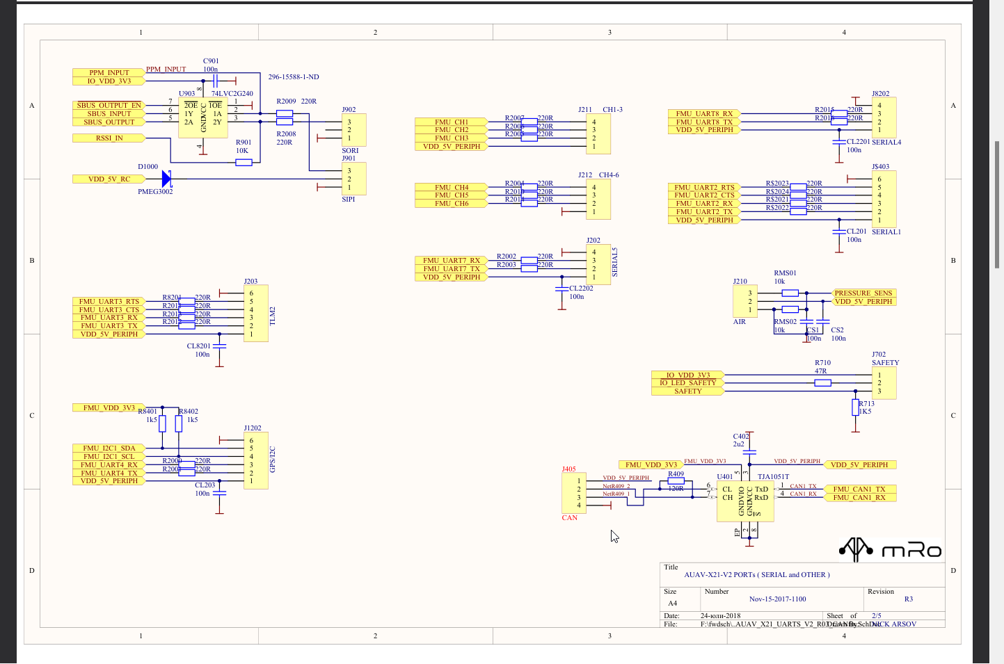
I was using a flight controller schematic as a reference for my study. It has a 220R series resistors between the MCU pin and port. I looked into it and guessed that they were series termination resistor. However, from what I've gathered, they were supposed to be placed near the driver. In the schematic, they were placed both at TX and RX. Can someone help me understand what they are for, where they are placed, and how were the value chosen?
-
\$\begingroup\$ Placement of components on a schematic is normally done "by function block". It has nothing to do with the placement in the layout. So "placing something near each other" is an instruction for creating the layout and not the schematic. \$\endgroup\$– kruemiCommented Aug 16 at 8:58
-
\$\begingroup\$ I meant that the resistor shouldn't be on RX, as it is not the driver, if those are series terminators. \$\endgroup\$– AvlKPCommented Aug 16 at 10:10
1 Answer
Series resistors are good for a number of things, depending on value.
In case of low resistance as in this case, the intention is most likely ESD protection. A series resistor isn't perfect ESD protection, but it helps a bit and is a whole lot cheaper than a TVS diode. So it's common good design practice to place low ohm series resistors on all signals leading to connectors or buttons/switches etc.
In case of high resistance series resistors, the intention is to protect a MCU or other IC against overcurrents or faults. Your schematics have some examples of this too, with 10k in series.

