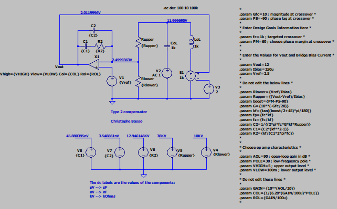
I am trying to build a isolated forward converter with voltage mode feedback. For some reason, I am unable to achieve required crossover frequency. To simplify everything, I have change the circuit to a buck converter. To simulate it, I am using LTspice with FRA analysis and LT1247 as a controller.
I am using the part in voltage mode as described in an article from TI (for similar part):
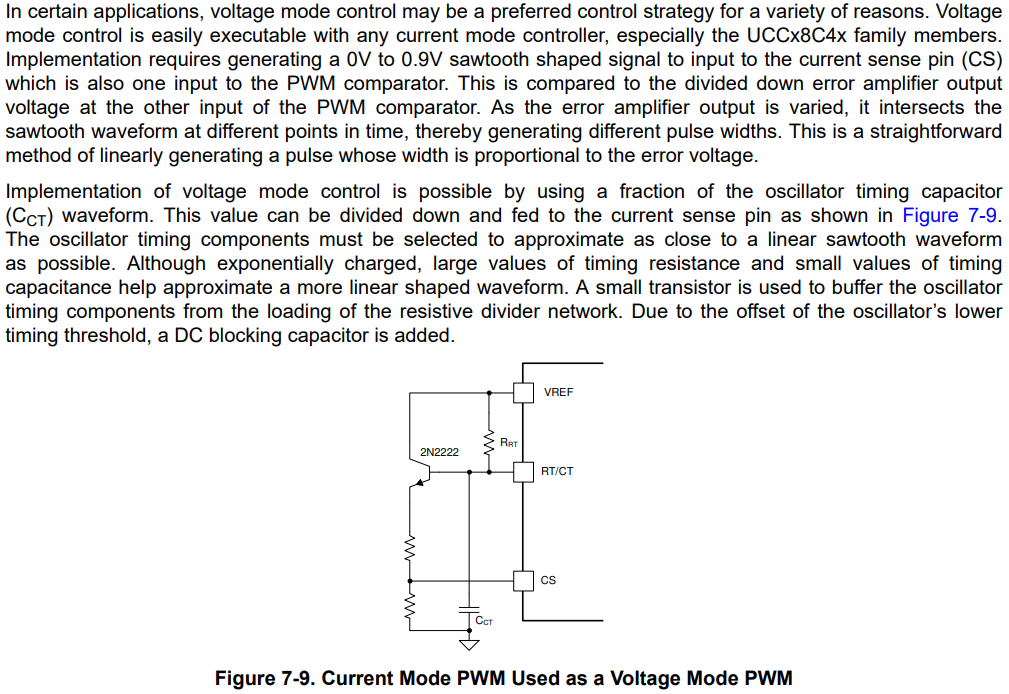
Designed parameters:
- Vin = 8 V
- Vout = 3.3 V
- Ioutmax = 1 A
- fsw = 200 kHz
- Lout = 100 µH
- Cout = 100 µF
As I am using ceramic capacitors, I assume ESR of output cap to be zero. And therefore I need a Type 3 compensator.
As the filter has a peak at 1.6 kHz, I put a double zero at half - 800 Hz. Double pole at half of the switching frequency - 100 kHz. Crossover frequency to the 10% of the switching frequency - 10 kHz.
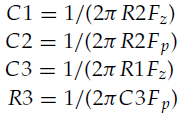
Then I use these equations to calculate all components:
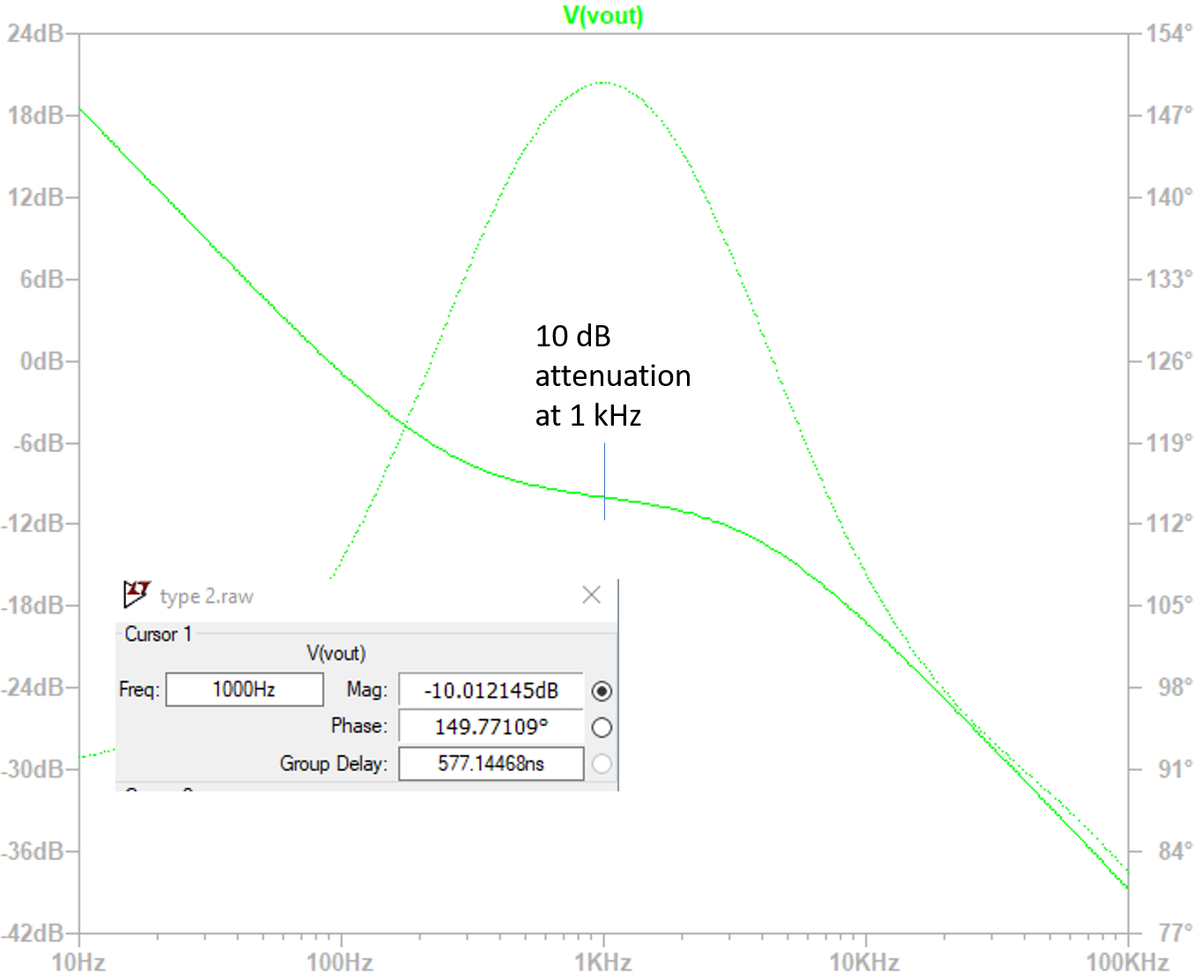
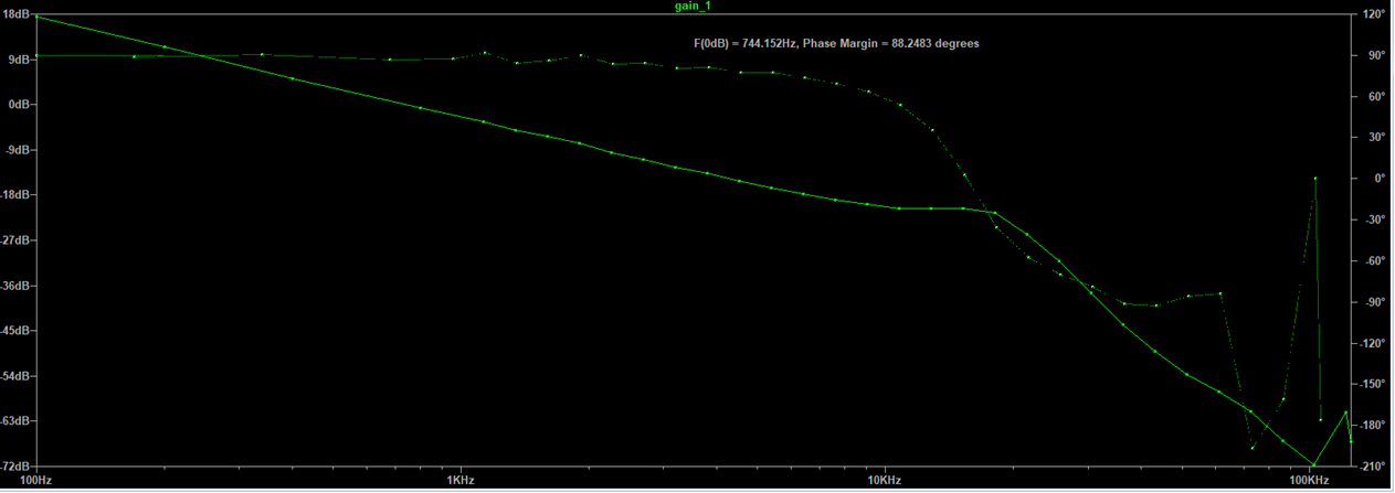
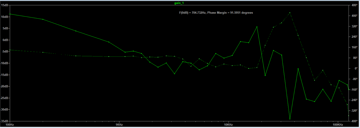
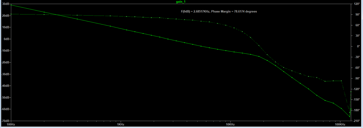
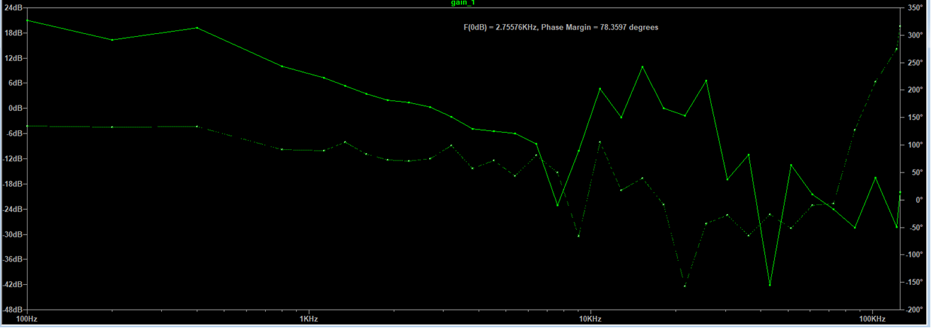
The problem is that when I simulate the circuit, no matter what I set as the gain of the EA, I always get the crossover frequency similar to the frequency of the double zero.
For gain = 10, fz = 800 Hz, fco = 10 kHz, fp = 100 kHz:
For gain = 100, fz = 800 Hz, fco = 10 kHz, fp = 100 kHz:
For gain = 10, fz = 3000 Hz, fco = 10 kHz, fp = 100 kHz:
For gain = 100, fz = 3000 Hz, fco = 10 kHz, fp = 100 kHz:
The simulated circuit for gain = 10, fz = 800 Hz, fco = 10 kHz, fp = 100 kHz:
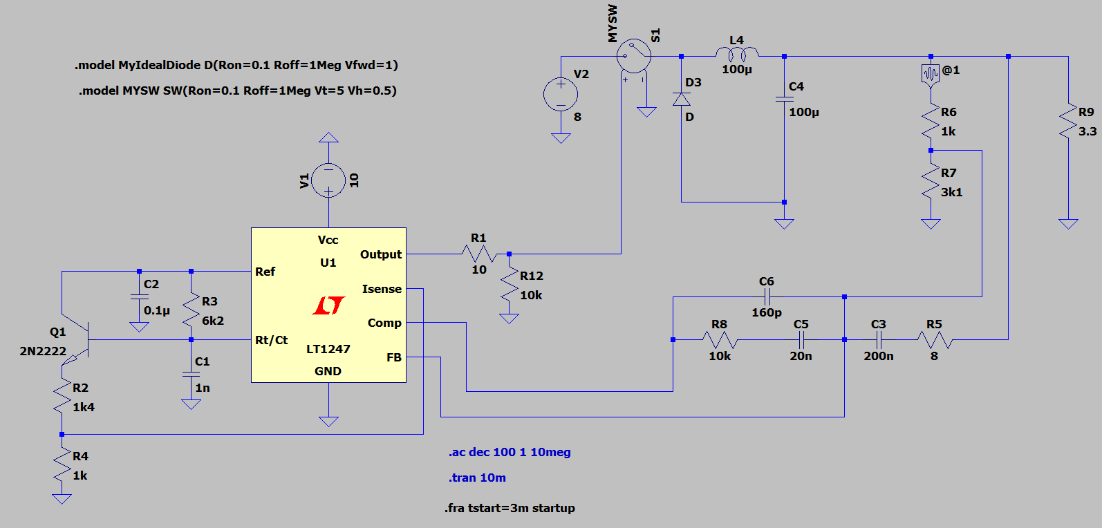
Link for download of the circuit: LTspice circuit
Can you please help me out where I made a mistake?
EDIT: I have changed the circuit to the one I have actually build. The results of the simulations are exactly the same.
I have calculated the gain of the power stage to be at low freq: Apwr = Vin / Vramp = 8/0.9 = 19 dB.
I also verified the gain by setting the gain of error amplifier to 1 and appling low frequency sin source to the amplifier and measured the output:
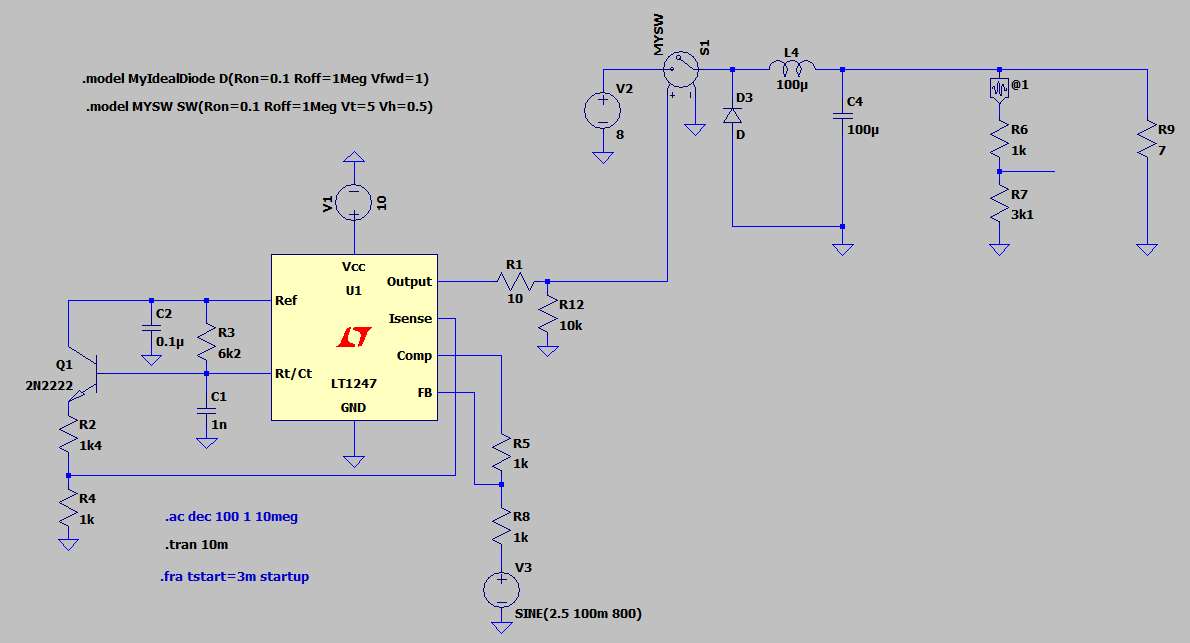
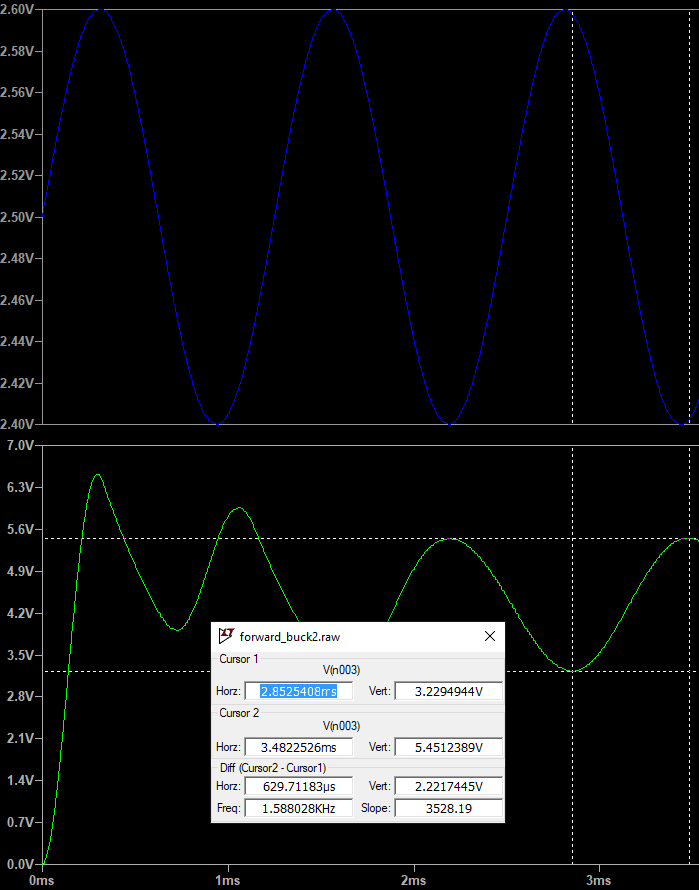
The simulated gain = 2.22/0.2 = 20 dB
I used the gain and LC filter parameters to simulate the circuit in Simplis:
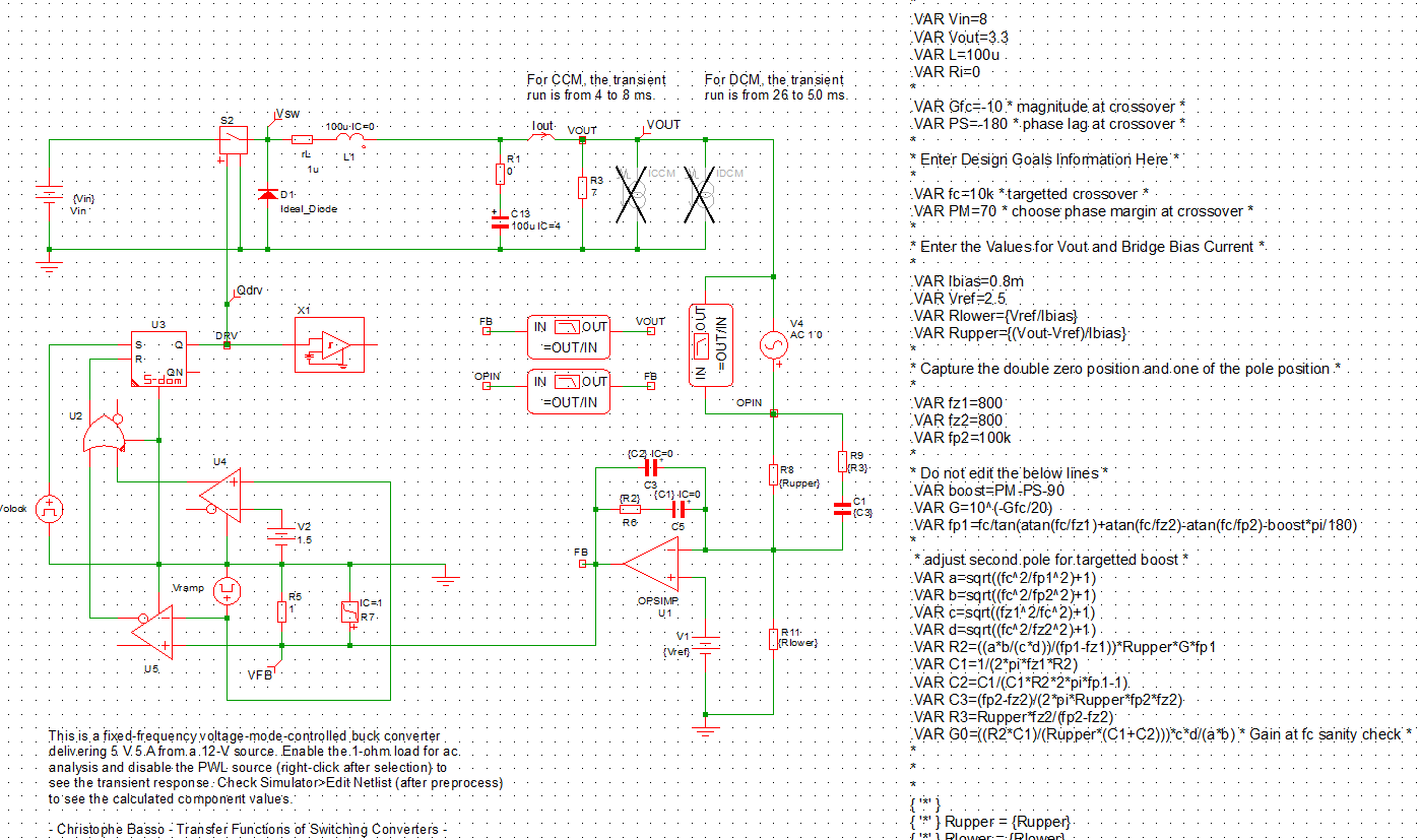 I had to lower the gain at crossover parameter a little bit to achieve desired frequency. The results:
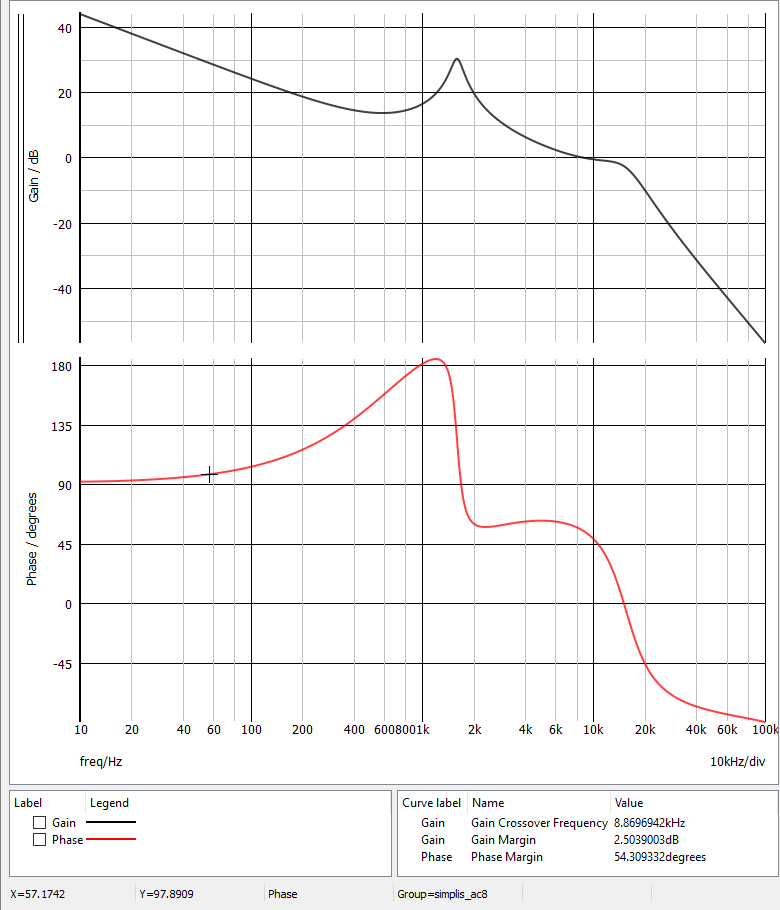
Then I used the calculated parameters to the LTspice circuit. Output voltage of the LC filter:
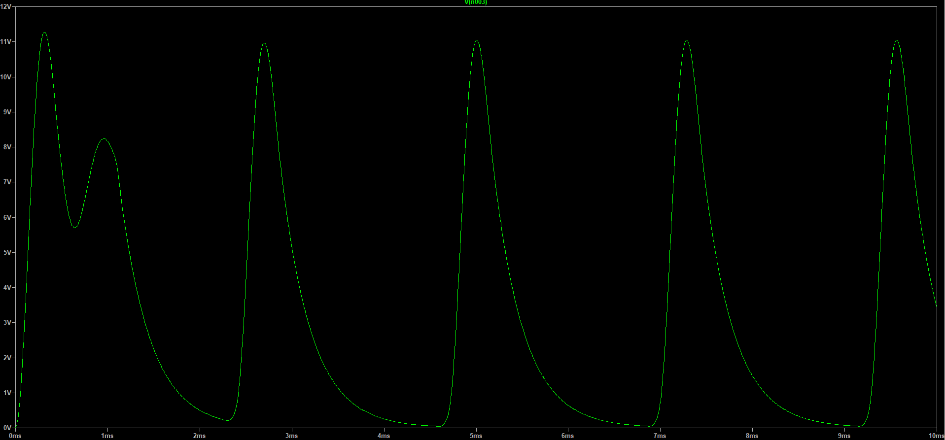
The problem is that with the same parameters the circuit is not stable and not able to achive the stable output voltage.
I have measured the circuit in the lab, the output voltage is stable, but I measured the crossover frequency to be about 300 Hz.
So what am I doing wrong? Thank you

