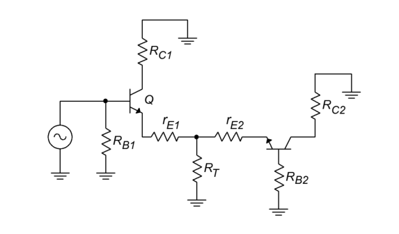
Why are \$R_{C1}\$ and \$R_{C2}\$ grounded while doing small signal analysis?
4 Answers
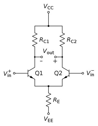
You don't show the original circuit, but based on the small signal equivalent and the description of it as a "differential amplifier" you are evidently talking about a circuit similar to this differential pair:
Source: Wikipedia
In small signal analysis DC sources are turned off, which means that DC voltage sources are set to 0 V (i.e. a short circuit) and DC current sources are set to 0 A (i.e. an open circuit). In a differential amplifier the collector resistors are connected directly to a DC voltage source (VCC in the above image); that source is turned off for AC small signal analysis (because its AC component is 0) so the collector resistors are grounded (0 V from ground is equivalent to ground).
-
\$\begingroup\$ Thanks for your answer@Null! Your answer make me to ask another question, what the significance of small signal analysis? or in other words what we try to understand from doing small signal analysis? \$\endgroup\$ Commented Oct 21, 2021 at 19:12
-
\$\begingroup\$ @Learner103 "Small signals" are those that are small enough for the circuit in question that the circuit behaves linearly, which we generally want in an amplifier. Large signals determine the bias parameters of the circuit but have non-linear effects. The idea is to analyze the DC operating point of a circuit to determine its small signal parameters, then analyze its (small signal) linear behavior (e.g. signal gain). \$\endgroup\$– Null ♦Commented Oct 21, 2021 at 19:18
-
\$\begingroup\$ Got it! So small signal analysis is just a theoretical model or can be done experimentally? If it can be done experimentally, then the circuit I have posted will it work and produce any output voltage as per theory? \$\endgroup\$ Commented Oct 21, 2021 at 19:31
-
\$\begingroup\$ @Learner103 You can verify it experimentally. Build the circuit and bias it with the DC sources you used in your small signal analysis, then apply a small signal to the input and you should see an output signal that matches what the small signal model predicted (assuming the small signal model was correct, and that the signal you applied was small enough for the circuit to behave linearly). \$\endgroup\$– Null ♦Commented Oct 21, 2021 at 19:38
-
\$\begingroup\$ @Learner103 The small signal goes a bit deeper than this discussion suggests (though it is good.) And it is a purely mathematical concept, not an experimental one. It's not that things behave linearly, by experimental result. It's that in mathematics all continuous portions of curves have a tangent line associated with every point. That tangent line is, by definition, linear. And finally, solving sets of non-linear equations is hard. Solving sets of linear equations is well understood and easy. That's why the concept is used. To simplify analysis. Not to meet experimental result. \$\endgroup\$– jonkCommented Oct 21, 2021 at 19:50
Under the condition of linear circuits, the super position principle/theorem allows you to turn off all voltage and current sources and turn on one voltage/current source at a time and the sum the effects of each individual source.
BJT can be considered linear components whenever the voltage and current sources of the circuit move the bias point by a small amount.
As the controlled current sources in the normal small signal model of all transistors have no parallel impedance, they are perfect current sources and whatever is on the collector side of them have no small signal effect on the emitter and base side of the circuit.
Thus, they are isolated from the rest of the circuit, so they can be left out of the analysis until you need those signals.
Differential vs static resistance
The zero differential resistance Rdiff = dV/dI of voltage sources and the infinite differential resistance of current sources are intrinsic properties, unaffected by whether the circuit is undergoing small-signal or large-signal analysis. These properties are always exhibited as long as there is a change in the input signal; hence the name "differential". At the same time, they have some "static" resistance R = V/I.
Experiments
This can be experimented in a simple way by connecting two different sources - one voltage and the other current - to each other. By varying the quantity produced by one of them, we can determine the differential resistance of the other.
Current source
Let's first supply the load through a current source...
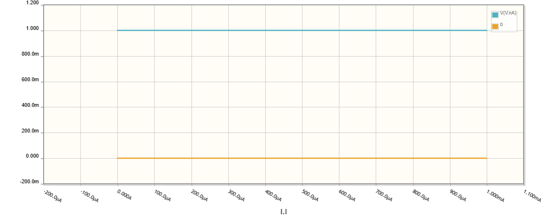
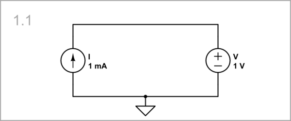
Voltage source as a load: ... and let the load be a voltage source. The static resistance is R = V/I = 1/1 = 1 kΩ. Figuratively speaking, the current source "sees" a 1 kΩ "resistor".
simulate this circuit – Schematic created using CircuitLab
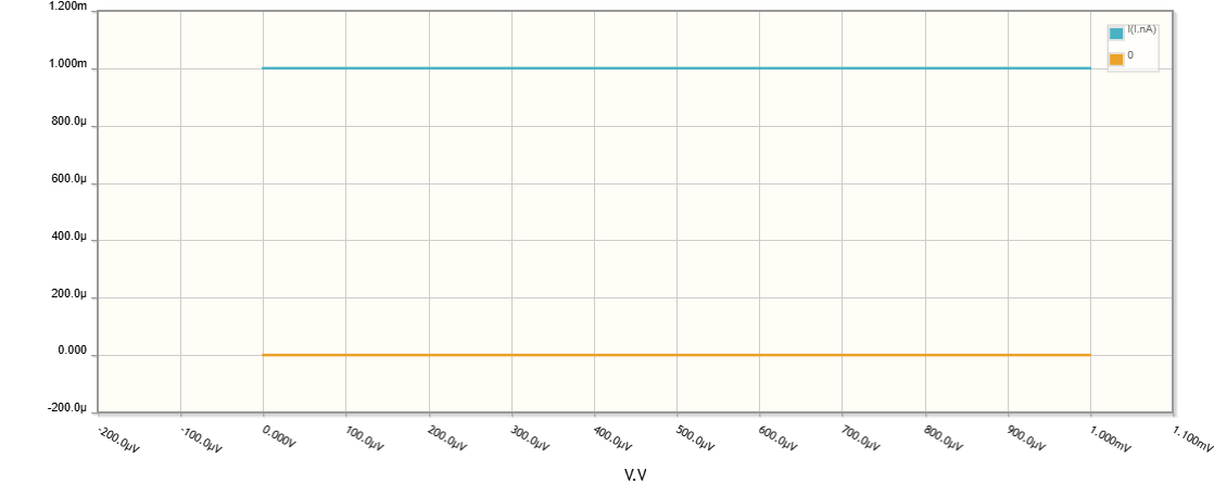
Because the voltage does not change when the current changes, the differential resistance Rdiff = dV/dI = 0/1 = 0. The current source "sees" an AC short circuit.
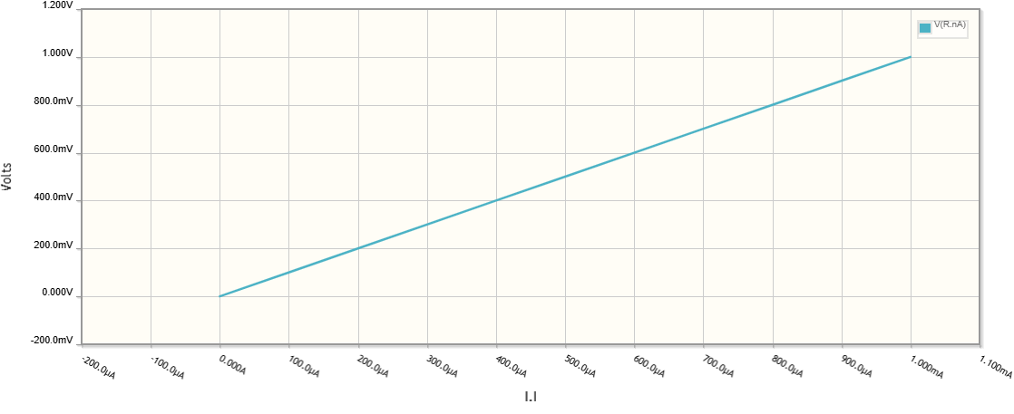
Resistor load: In this case, the differential resistance is identical to the static resistance - Rdiff = dV/dI = R = V/I = 1 kΩ. The voltage source "sees" a 1 kΩ resistor.
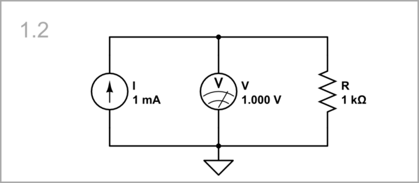
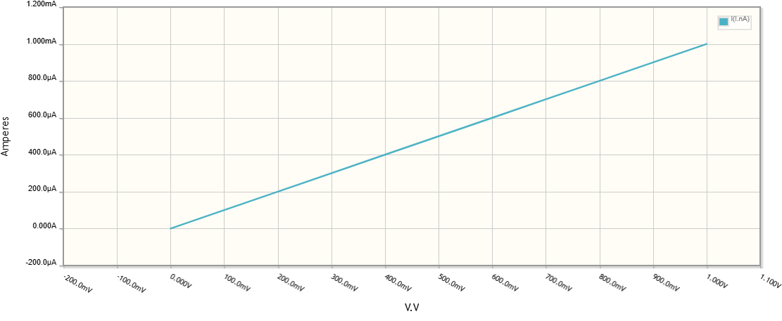
The voltage is proportional to current (Ohm's law).
Voltage source
Now let's supply the load through a voltage source...
Current source as a load ... and let the load be a current source. The static resistance is again R = V/I = 1/1 = 1 kΩ. The voltage source "sees" a 1 kΩ "resistor".
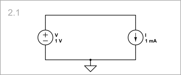
Because the current does not change when the voltage changes, the differential resistance Rdiff = dV/dI = 1/0 -> ∞. The voltage source "sees" an AC open circuit.
Resistor load: As above, in this case, the differential resistance is identical to the static resistance - Rdiff = dV/dI = R = V/R = 1 kΩ. The voltage source "sees" a 1 kΩ resistor.
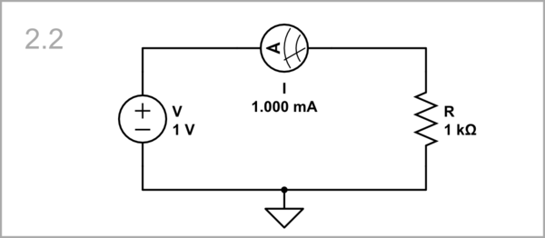
The current is proportional to voltage (Ohm's law).

