5
\$\begingroup\$

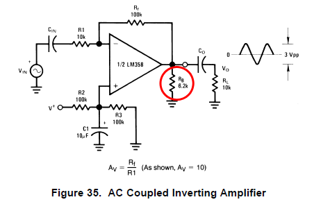
I have a few questions about the LM358. The first is regard to the schematic below. I'd like to know why RB is there? (What purpose does it serve and how do you know?)
enter image description here

The second is with regard to the figure below showing open-loop response. I don't quite understand why there is feedback (the cap and the 10M resistor). Could someone please explain why?

OpenLoop

My last is, how does one know what the maximum frequency that one can put into an op-amp is? For example, I think I read somewhere that tying a terminal to a square pulse generator is bad because the square pulse has an infinite bandwidth and putting something with infinite bandwidth into an op-amp is not good. How does one know how high a frequency an op-amp is rated for (without breaking it)?

\$\endgroup\$
2
  • \$\begingroup\$ I speculate for #1 that Rb is there to provide some frequency-independent load to the op-amp output - the capacitor impedance will increase as the frequency decreases towards DC. For #2, the cap is an AC coupling cap and I speculate that the 10 Meg resistor is there just to give something to measure the gain across (it's not a feedback resistor per se, since it's not defining any gain - this isn't a normal inverting or non-inverting amplifier setup). For #3, see #2 - Vin is a sinusoidal source, not a square wave source. \$\endgroup\$ Commented Jun 21, 2013 at 13:41
  • 1
    \$\begingroup\$ If you have three questions, you can ask three questions, in separate questions. If you put them all together like this, it's harder to answer. \$\endgroup\$
    – Phil Frost
    Commented Jun 21, 2013 at 14:12

3 Answers 3

2
\$\begingroup\$

Here's what the application hints say about Rload

enter image description here

I don't quite understand why there is feedback (the cap and the 10M resistor). Could someone please explain why?

Because the input offset voltage can be a few millivolt it's easy to apply a 10M feedback resistor to perfectly bias the op-amp DC wise so that ac measurements can be made. Becuase the input cap is 0.1uF and the feedback resistor is 10Mohm the circuit acts like a high pass filter at 0.159Hz so this is of no consequence when measuring ac gain. The real gain of the opamp can be inferred from the gain when using C and R.

how does one know what the maximum frequency that one can put into an op-amp is?

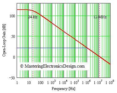
Here is an open loop gain (red) from an op-amp not disimilar to the LM358. Notice the blue line - this is the frequency response when negative feedback is applied. There is a constant 20 dB gain from DC to 1MHz (3dB down) and this would be the actual response with feedback. So if your square wave were 1kHz the square would be failry pure up to nearly the 1000th harmonic.

You can't break an op-amp with frequency - you can only break it with too much current or voltage.

enter image description here

\$\endgroup\$
2
\$\begingroup\$

I'm only going to answer one of your questions. It would be better if you asked your questions separately.

My last is, how does one know what the maximum frequency that one can put into an op-amp is?

This is specified in the datasheet. Applying a frequency beyond the op-amp's specifications won't harm it. The limitation is simply that as frequency increases, the op-amp's gain decreases. Essentially, it is a low-pass filter. The image from your question illustrates this:

frequency response

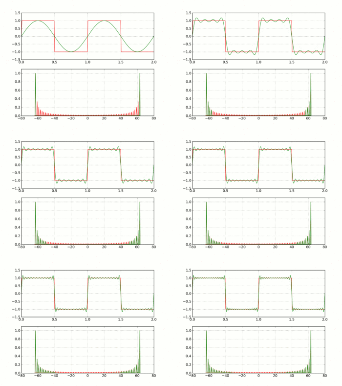
If your input square wave is very much below the op-amp's cutoff frequency, then it will pass through unchanged. As the cutoff frequency gets closer to the square wave frequency, it begins attenuating the higher harmonics, which has the effect of increasing the rise and fall times. Eventually, all the harmonics will be attenuated, and the square wave will start looking more like a sine wave. As the square wave frequency increases beyond the op-amp's cutoff frequency, the entire signal is attenuated, until you are left with nothing at all.

Here's an animation from Wikipedia showing the shape of the square wave as higher harmonics are added. The process I described is the same thing, but in reverse: the higher harmonics are attenuated.

square wave synthesis

\$\endgroup\$
1
\$\begingroup\$

The resistor is also at the output to act as a pull-down. The LM358 is not a rail to rail op-amp, so without that resistor you will not be able to have your output signal hit ground. You could alternatively place that resistor as a pull-up from output to V+ if you needed your signal to reach closer to V+ without clipping.

\$\endgroup\$

Your Answer

By clicking “Post Your Answer”, you agree to our terms of service and acknowledge you have read our privacy policy.

Not the answer you're looking for? Browse other questions tagged or ask your own question.