0
\$\begingroup\$

I need to wire 5 led's in series with a switch and variable resistor to control brightness.

These I think

I think the circuit will need to look something like this (Ignoring the values the editor added!) but it's been a very long time since I've done anything like this.
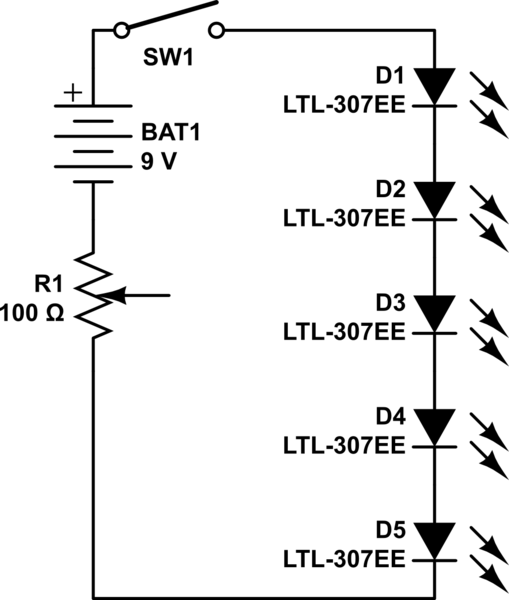
schematic

simulate this circuit – Schematic created using CircuitLab

I don't know how to calculate how much battery power will be required, or if it will need additional resistence.

How do you go about solving these kinds of equations?

\$\endgroup\$
6
  • \$\begingroup\$ I'll put the resistor before the first LED, after the switch \$\endgroup\$ Commented Sep 18, 2013 at 13:53
  • \$\begingroup\$ @KingsInnerSoul How exactly does the position of the resistor matter? \$\endgroup\$ Commented Sep 18, 2013 at 13:53
  • 1
    \$\begingroup\$ I'm assuming you will attach the wiper to either end of the potentiometer. You should also add an additional series resistor to set the maximum current allowed when the potentiometer is set to zero ohms. This is the "smallest value of resistance" referred to in Brian's answer. This will protect your LEDs. \$\endgroup\$
    – Tut
    Commented Sep 18, 2013 at 13:56
  • \$\begingroup\$ a convention which i am used to, and thats how I usually see them in many other schematics. \$\endgroup\$ Commented Sep 18, 2013 at 13:57
  • \$\begingroup\$ @KingsInnerSoul Current flow convention has nothing to do with resistor position convention. Neither is there any recognized convention for which side a resistor goes in, nor does it make the least bit of difference to circuit operation. Your comment merely confuses EE-inexperienced readers, while adding no value whatsoever. \$\endgroup\$ Commented Sep 18, 2013 at 14:05

1 Answer 1

3
\$\begingroup\$

The product summary tells you the typical and max. forward voltage and maximum current.

Multiply typical and max. voltages by no. of LEDs, then choose a power source (battery) with higher voltage than max * no. of LEDs.

Subtract typical voltage * no. of LEDs from battery voltage; this is the voltage you can expect across the resistor.

Divide that voltage by the max. operating current to give you the smallest value of resistance you need. You can increase it to reduce brightness.

\$\endgroup\$
11
  • \$\begingroup\$ That sounds great! I'll run these numbers later today. Really appreciated. \$\endgroup\$
    – asawyer
    Commented Sep 18, 2013 at 13:58
  • \$\begingroup\$ Divide that voltage by the max. operating current How do you determine max operating current? \$\endgroup\$
    – asawyer
    Commented Sep 18, 2013 at 16:20
  • \$\begingroup\$ See first line of answer. The product summary is on the page you linked to. \$\endgroup\$
    – user16324
    Commented Sep 18, 2013 at 16:37
  • 1
    \$\begingroup\$ The math is OK but 0.5V/0.02A = 25 ohms is the resistor you would ask for. HOWEVER if the LEDs you get have Vmax=4V ... 18V < 20V so no light. Which is why Vmax determines your supply ... in your case, 27V and take it from there. \$\endgroup\$
    – user16324
    Commented Sep 18, 2013 at 17:11
  • 1
    \$\begingroup\$ You got it right. But to explain: when designing, you have to take variability into account. 100 ohms could over-stress "typical" LEDs (with a fresh battery!) though you might get away with it. 200 ohms would be safe under all combinations of LED at a (surprisingly small) cost in brightness (and more battery life!) The answer is a shorthand process to accomplish that : the comments explain why. \$\endgroup\$
    – user16324
    Commented Sep 19, 2013 at 8:01

Not the answer you're looking for? Browse other questions tagged or ask your own question.