14
\$\begingroup\$

In my project, I use a use an RF transmitter and receiver.

One of the RF components seemed to fail because the connection between my Arduinos no longer works. I cannot determine whether the RF receiver or transmitter works.

I want to see if my RF transmitter gives an output, but I do not own an oscilloscope to view it's waves.

I've seen this answer, but it only shows if the Arduino is sending data to the RF transmitter. Is there any alternative way to check if the RF transmitter works or not?

\$\endgroup\$
2
  • \$\begingroup\$ You should be able to make a small loop antenna ("sniffer") with a UHF diode and capacitor. Connect this to a voltmeter on DC and hold the loop close the rf transmitter. You should see a hundred milli volts when/if it is transmitting. \$\endgroup\$
    – Andy aka
    Commented Aug 9, 2013 at 22:38
  • 1
    \$\begingroup\$ This thing detects approximately 1 mS bursts of 2.4 GHz from a nRF2401 type transceiver. <harborfreight.com/wireless-camera-rf-detector-95053.html> \$\endgroup\$
    – user28936
    Commented Sep 12, 2013 at 6:10

1 Answer 1

15
\$\begingroup\$

Build a simple detector with some diodes:
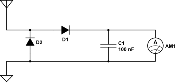
schematic

simulate this circuit – Schematic created using CircuitLab

If you just want to know if there is some signal, and aren't concerned with accurately measuring its strength, or demodulating it, you can throw this together with just about any components and it will work. Ideally the diodes have a low forward voltage, so they are Schottky diodes, like 1N60, or 1N5711, or a germanium diode. If you don't have any of those, probably an ordinary 1N4148 works too. Use whatever you have.

The capacitor is also not terribly critical. A cheap ceramic disk capacitor will work fine; whatever value you have.

The antenna is just a piece of wire. Connect the ground to something else, like your Arduino's ground, or the case, or another piece of wire. Not especially critical.

The hardest part is probably the ammeter. This needs to be a very sensitive meter -- on the order of microamps. Ideally, an analog meter, since it will be easier to see the changes in signal strength. A digital meter will work also, if it has a low enough range. It will just be harder to read.

Test the circuit by putting the antenna near a source of noise, like a computer monitor, or a motor, or your wireless access point, or your laptop's WiFi antenna, or any other radio transmitter you have that you know works.

Then, put it near your RF transmitter. Try transmitting something. If the ammeter moves, it's transmitting something.

\$\endgroup\$
2
  • \$\begingroup\$ Thanks for your answer! Just to clarify, is the ground connected to earth or my circuit? \$\endgroup\$
    – slippery
    Commented Aug 10, 2013 at 17:01
  • 2
    \$\begingroup\$ @zeldarulez either. It doesn't even have to be connected to anything, really. You could just make it another wire, and then you have a dipole antenna. \$\endgroup\$
    – Phil Frost
    Commented Aug 11, 2013 at 1:55

Your Answer

By clicking “Post Your Answer”, you agree to our terms of service and acknowledge you have read our privacy policy.

Not the answer you're looking for? Browse other questions tagged or ask your own question.