7
\$\begingroup\$

We are developing an industrial controls product that will be used to monitor the presence or absence of voltage ranging from 5V to 480V. Since the unit will be generic and programmable, this input may be used in a variety of unpredictable ways.

The problem I have been wrestling with is how to monitor such a wide range of voltages with a single circuit design. For example, if I drive an optocoupler LED directly, I can't get the 5V to turn it on without the 480V destroying it. Voltage regulators typically operate on much lower voltage than 480V, so I'm in a bit of a dilemma.

The industrial controls solutions I've seen get around this problem by saying, "purchase this other model for high voltage input" or "buy this high voltage input converter and add it on." Is that really the only solution here? Am I trying to do the impossible? Any input would be appreciated, no pun intended!

A possibly related question

\$\endgroup\$
9
  • \$\begingroup\$ Is it a dc line or ac? Once a unit has been "commissioned" is it likely that the input full range can suddenly become 5V when it was formerly 480V or is it an installation fixed thing? \$\endgroup\$
    – Andy aka
    Commented Mar 10, 2014 at 22:09
  • \$\begingroup\$ The input will go through a bridge rectifier, so it will all be treated as DC... I think I see where you're going, though. How do you detect failure modes if 5V looks the same as 480V? \$\endgroup\$ Commented Mar 10, 2014 at 22:20
  • \$\begingroup\$ no I wasn't implying or suggesting, just asking if an installation is setup at 480v would it remain as this or could it be reasonably expected to go much lower and not be in a fault condition. It might help if you explain a bit more about a typical installation. \$\endgroup\$
    – Andy aka
    Commented Mar 10, 2014 at 22:35
  • \$\begingroup\$ I guess that's the whole point... we don't know what a typical installation will look like. The customer will hook it up to whatever they want to monitor. \$\endgroup\$ Commented Mar 10, 2014 at 22:40
  • 1
    \$\begingroup\$ I think you'll need at least 10mm creepage distance for 480VAC. There are adequately rated resistors for Olin's approach, try Vishay. \$\endgroup\$ Commented Mar 10, 2014 at 23:28

5 Answers 5

8
\$\begingroup\$

You should be able to do this if you think of this input voltage as a analog signal. Attenuate it by 100, and you have something in the 0-5 V range. 5 V in results in only 50 mV, but that is still plenty high enough to detect above any reasonable noise floor.

It might be a good idea to run this into a micro to actually measure the voltage, then have the code decide whether the input voltage is really "present" or not. With such a 100:1 range, I expect it's not as simple as just checking whether it's over 4 V, for example, or not. The code can hopefully check what the expected level is, perhaps see that it is fairly steady, or whatever. Keep in mind that a line that is at 480 V when "on", might have more than 5 V of noise on it when off. I think some logic that does more than just a dumb fixed threshold comparison will be useful.

Due to the high voltage, you want to use a high impedance divider else it will dissipate significant power. 1 MΩ top resistor and 10 kΩ bottom resistor sounds like it might work. That's not quite 1/4 W at 480 V in, and of course much less at lower voltages. It also provides 10 kΩ impedance output to drive the A/D input with.

\$\endgroup\$
9
  • \$\begingroup\$ Thanks, Olin. The only downside I can see is the inability to insert isolation, but that may not matter if we're using a 1M resistor. What are your thoughts? \$\endgroup\$ Commented Mar 10, 2014 at 22:16
  • \$\begingroup\$ You can always have the isolation by using a small micro controller on the 'hot' side of an opto-isolator. \$\endgroup\$ Commented Mar 10, 2014 at 22:35
  • \$\begingroup\$ @Wouter, I thought about that, but that would require me to provide power to the uC from the hot side, which in turn needs a vreg capable of 1000V input... If I could do that, this problem would be solved! :-) \$\endgroup\$ Commented Mar 10, 2014 at 22:44
  • \$\begingroup\$ @Olin, we can provide some "poor man's isolation" by splitting the 1M into two 500K's and putting them on incoming V+ and V-. That would eliminate the need for optoisolators, I think. \$\endgroup\$ Commented Mar 10, 2014 at 22:51
  • 1
    \$\begingroup\$ You could provide the power from a low voltage side using a high-isolation-voltage DC-DC converter, not from the input signal. \$\endgroup\$ Commented Mar 10, 2014 at 22:52
7
\$\begingroup\$

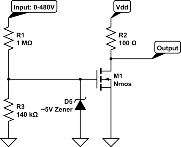
The voltage divider R1,R3 needs to create approximately the threshold voltage of the Nmos which is usually around 0.7V when the input is 5V. The Zener diode is there to protect the Nmos gate so anything above the chosen Zener voltage just gets dropped straight to ground. This allows a very broad input range. R1 needs to have about 1Mohm or higher resistance to prevent too much current flow on the input side. The output is a simple common-source inverting amplifier output. R2 should be matched to whatever output current you desire, i.e. Vdd/R2=I. Make sure Vdd is NOT the same as your input signal. It should be at a level that M1 can handle.

The way this circuit works is between 0-5 Volts the voltage divider should not provide a voltage high enough to reach the threshold voltage of the Nmos. Above 5 volts the threshold voltage is reached, the nmos turns on and drives the output to ground. If the input gets really high and the voltage divider starts passing through too high of a voltage, the Zener diode "kicks in" and limits the input voltage to, in this case 5V max.

The 5V threshold isn't terribly accurate as threshold voltages on mosfets are prone to vary depending on the process that made them. If greater accuracy is needed, I'd head towards an op-amp solution unless the digital solutions mentioned in the other answers work as well.

schematic

simulate this circuit – Schematic created using CircuitLab

\$\endgroup\$
2
\$\begingroup\$

I think your voltage range will be hard to achieve with one circuit.

I have made industrial inputs that were robust for inputs in the range of 0 to about 50V. I used an optocoupler LED as the input. Instead of using a resistor to bias the optocoupler I used a current regulator diode in front of the LED which leads to linear increase of power dissipation in the bias component as voltage increases instead of a squared increase like you get with a resistor.

I've used a slightly different strategy for sensing high voltages with an optocoupler. I'll post the circuit of that shortly.

\$\endgroup\$
1
\$\begingroup\$

Current limiting/regulating diodes are great, I tackled a similar problem a while ago so thought I would share my findings:

I used a rectifier into several current limiting diodes in series to control an opto-isolator. The Semitec E-202 passes 0.5-2 mA across a voltage range of 0.5 to 100V. Six E-202s in series into a Vishay SFH618 Opto should pass 0.5 mA fairly easily (assuming something like 3.3V or 5V available for opto supply).

There isn't a ton of wiggle room and your output signal will be fairly small, but you'll have very good isolation and reliable sensing of presence/absence of voltage between about 4.5V and 600V (remember 480 Vrms gives you 580Vdc out of the rectifier).

\$\endgroup\$
2
  • \$\begingroup\$ 480v * 1.414 = 670 volts peak \$\endgroup\$
    – Marla
    Commented May 29, 2014 at 15:17
  • \$\begingroup\$ Thanks for the specific info! I'll have to look into that. \$\endgroup\$ Commented May 29, 2014 at 15:50
0
\$\begingroup\$

TI has a quite a good solution that can help you sense up to 350V DC. The idea is to limit current by a resistor and additonal current limiting circuitry:

Interfacing high-voltage applications to low-power controllers

\$\endgroup\$

Your Answer

By clicking “Post Your Answer”, you agree to our terms of service and acknowledge you have read our privacy policy.

Not the answer you're looking for? Browse other questions tagged or ask your own question.